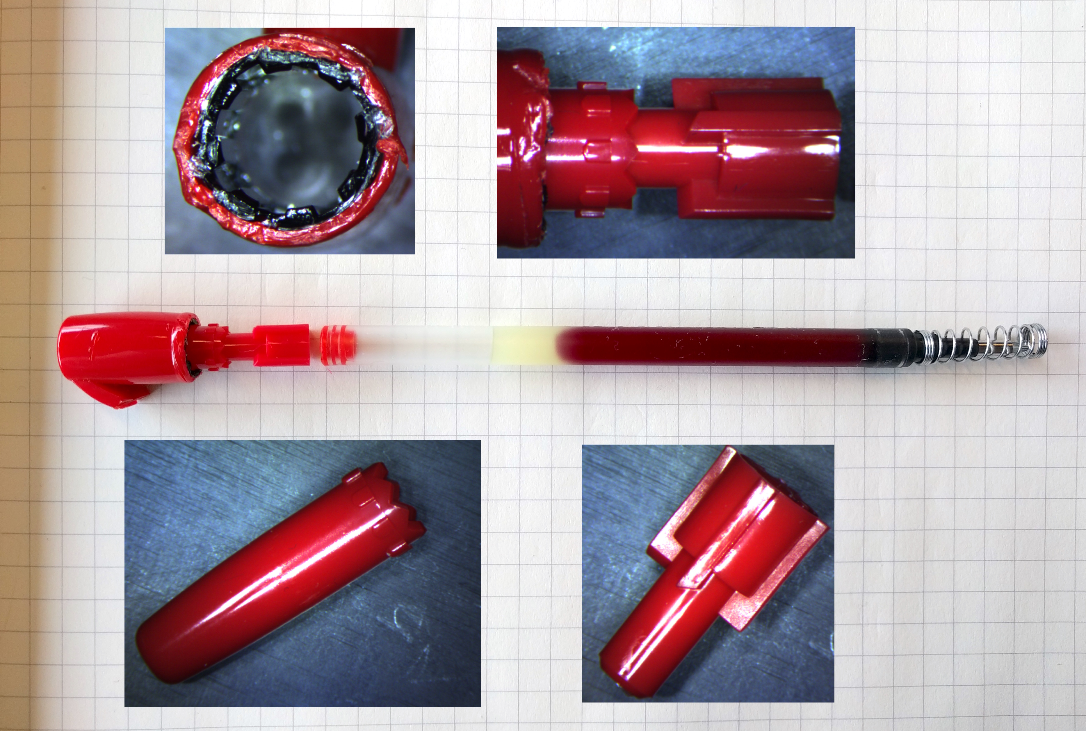
A clicky pen uses three main components. The internal diameter of the shaft (shown top left) is circularly castellated with two different depths. As the plunger rotates around it can slide down within alternate notches to allow the pen to retract on alternate movements. The plunger and other piece have 45 degree surfaces that interact during the click to induce the rotation. A spring provides the returning force.
The thinking is that this could be scaled up, and combined with a solenoid to provide a holding force, thereby ensuring that power is only required to transition from one state to another and not to remain in the state. The design requirement would therefore be a solenoid that can click the mechanism in and out.
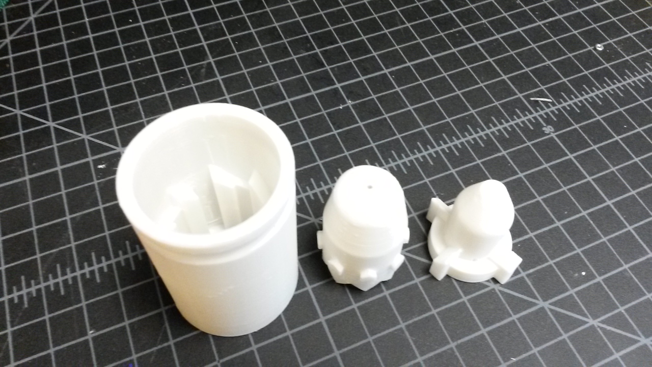
The clicking mechanism is made from 3 main parts, which I am calling the tube, push-top and plunger. The images below show these parts from the top and bottom. The tube remains stationary, the push-top moves longitudinally and the plunger moves longitudinally and rotationally.
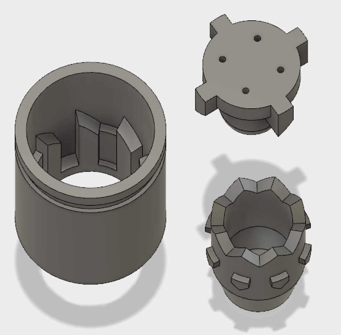
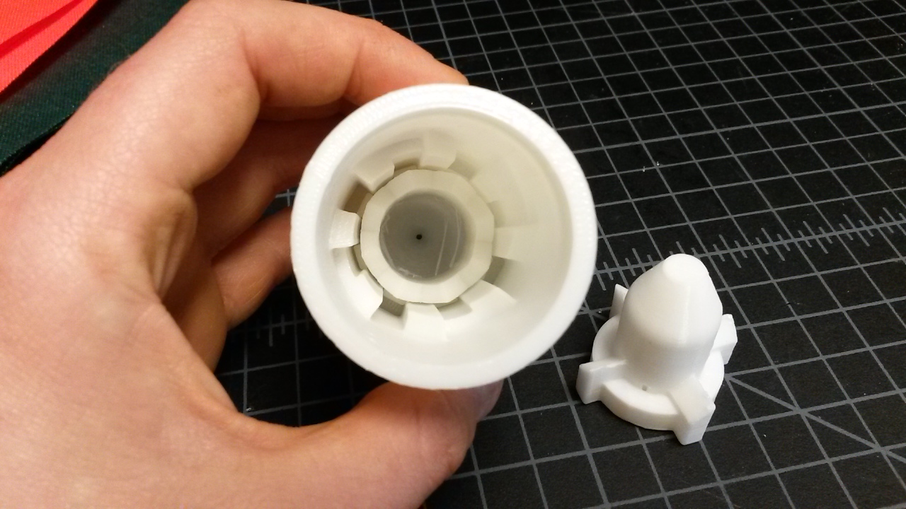
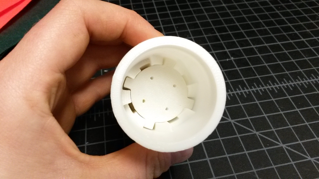
There are two sets of geometry within each part that work together to create the binary actuation. The images below show how different castellated cylindrical sections are used with the parts. In addition, the diagonal features of the parts work in tandem on constrain the parts as required.
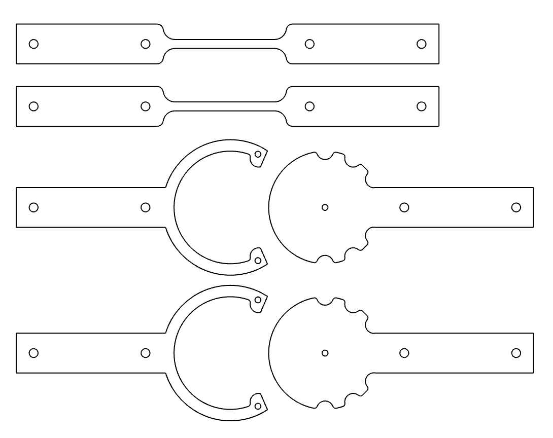
The range of motion between the stable states is a function of the geometry shown in the images below. The left drawing is the parts inline in the down position and the right is the parts inline in the up position. These drawings show that the range of motion is equal to difference between z1 and z3. There is a lower limit to the z1 to ensure that it remains within the channels of the tube. Therefore the best way to increase the range of motion is to increase the length of the channels with the tube part.
After a lot of redesigns and 3D prints, I came up with the following pieces.
The click pen mechanism is bistable in one direction as demonstrated in the video above. When applying a load to the bolt towards the mechanism, the holding force is generated by the teeth of the plunger butting up against surfaces in the tube. However if the force is applied in the opposite direction then the resistive force is only that provided by the spring. It is possible to increase this force by using a stiffer spring however this would also increase the load requirement of the acutator that is moving the mechanism between the two states. Therefore this mechanism might be termed a unidirectional bistable mechanism.
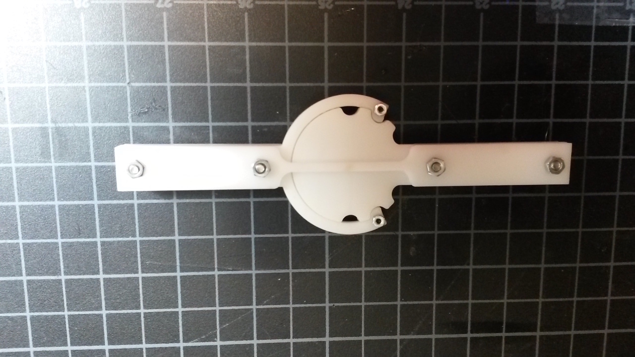
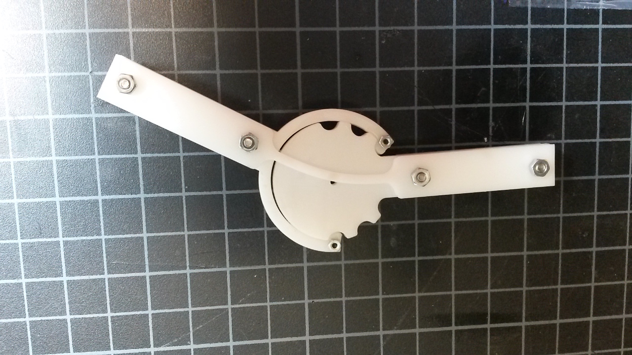
Taking ideas from the work presented above, this mechanism below has 3 stable positions, held in place by elastic fingers nested inside of detents. The fingers and detents are sandwiched between two flexure beams that provide rigidity along the axis of the joint. It would be possible to adjust the transition energy of this mechanism by varying the thickness of the fingers and the depths of the detents. Furthermore, it is possible to add additional stable states by increasing the number of pairs of detents. The fingers have a tendency to pop out of place, therefore it might be necessary to add guides to keep them wrapped around the detents.
It might be possible to incorporate this concept into the laminated flexural pieces, thereby removing the need to incorpoate the bistability with the motor.
When we design our lattice structures we want them to be (bucking or stretch??) dominated. This quantity defines maximum force that the structure can withstand. If we design a structure with bistable joints we want them to have the same holding force as the designed limit of the material. This means that they will require a transition force greater that then maximum force that the structure can withstand. This thinking mainly applies to structures that are equally loaded in it's different configurations, such as a shape morphed aircraft wing.
The requirements might be less stringent when the cellular solid isn't being used close to it's maximum strength although in general with these structures we're looking for applications where specific stiffness is important