The most efficient form of a sun collector requires a parabolic shape. Total internal reflection means that the angle of incidence (angle between sun and surface normal) equals the angle of reflection (angle between surface normal and reflected beam). When experienced within a parabola, all reflections focus at a single point.
In order to compensate for a changing sun angle, you need to rotate the entire parabola. To change the focus point then you need to change the parabolas shape.
It might be possible to utilize a fresnel mirror to discretize a sun collector and design in deformation modes for each of the mirror segments that allow a single degree of freedom to maintain a constant focal point as the sun moves overhead.
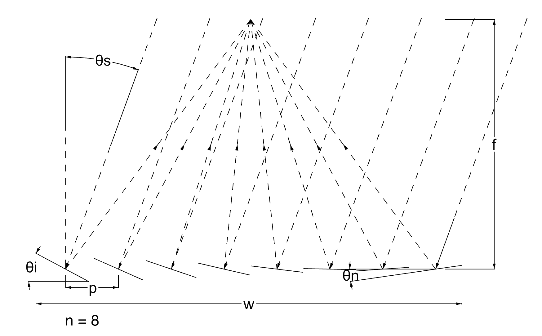
$w$ = width of trough
$n$ = number of segments
$p$ = distance between segments = $w/n$
$f$ = height of focal point
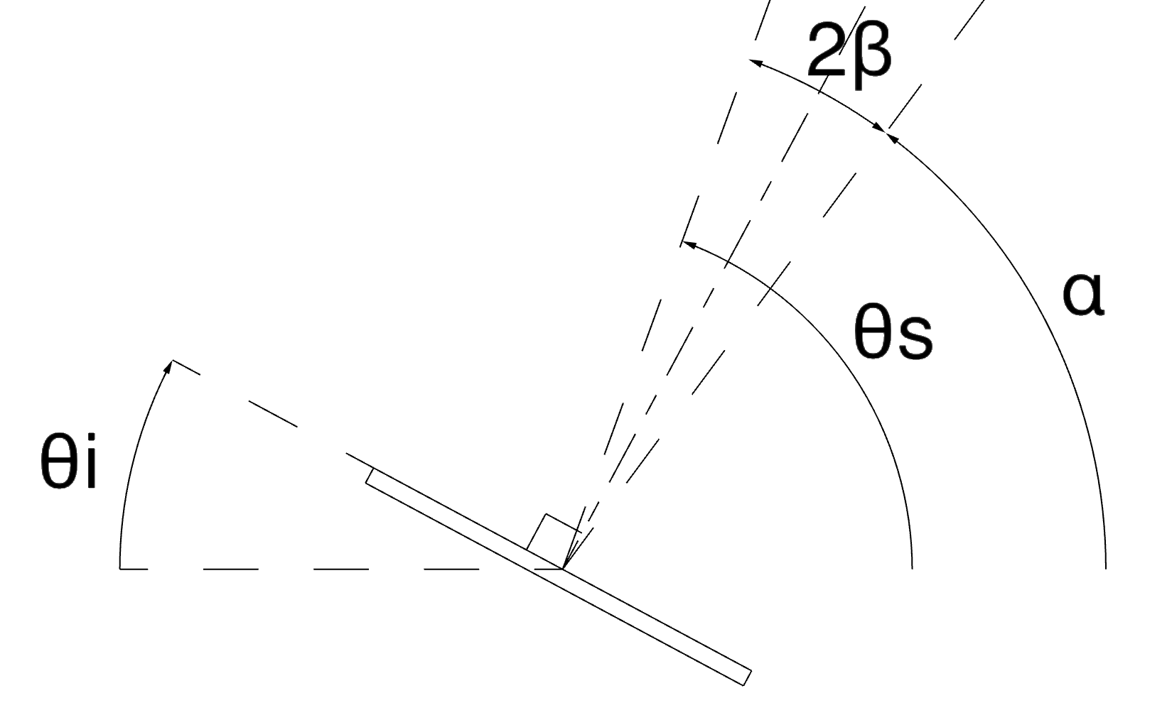
$\beta_i$ = angle of reflection
$\theta_s$ = angle of sun's rays
$\theta_i$ = angle of reflective segment below the horizontal, taken about the right edge
To find $\theta_i$
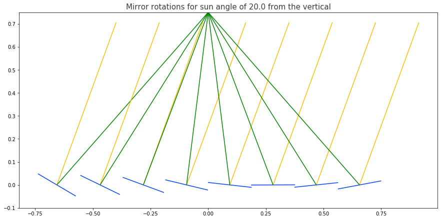
$$ \alpha = tan^{-1} \Bigg( \frac{f}{p \left(i - \frac{n+1}{2} \right)} \Bigg)$$ $$ \beta = \frac{\theta_s - \alpha}{2}$$ $$ \theta_i = \pi/2 - \alpha - \beta$$Using these equations I created a Jupyter notebook to output angles and a plot of the discretized mirror for various sun angles. It was important to use the numpy arctan2 function to maintain reference to the quadrant that the output angle fell within.
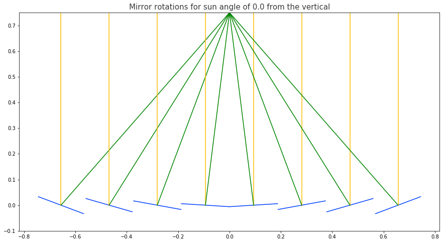
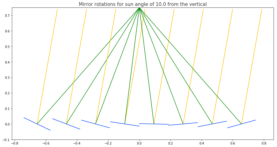
For a +/- 20 degree angle change, the outer mirrors need to move between limits of 10.6 degress and 30.6 degrees whilst remaining within the same quadrant. The central mirrors have to change their angle of reflection betwee different quadrants meaning that the underlying frame would require a different deformation mode to the frame supporting the outer mirrors.
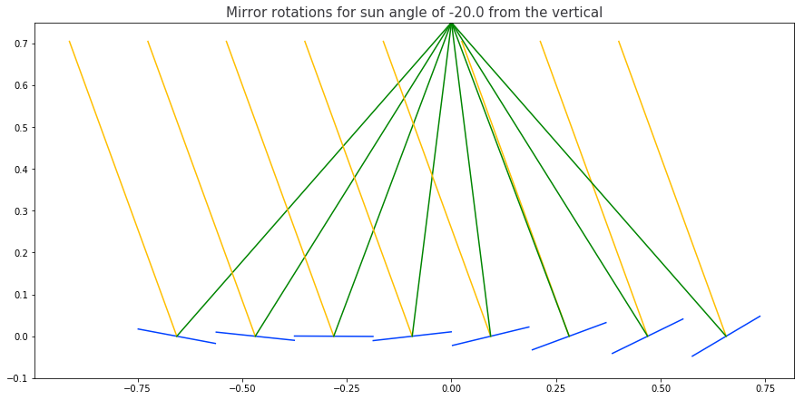
For a +/- 30 degree angle change, the outer mirrors need to move between limits of 5.6 degress and 35.6 degrees.
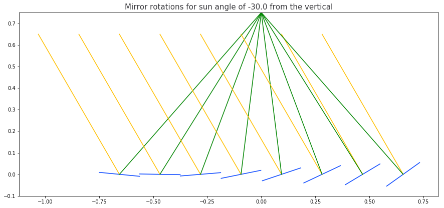
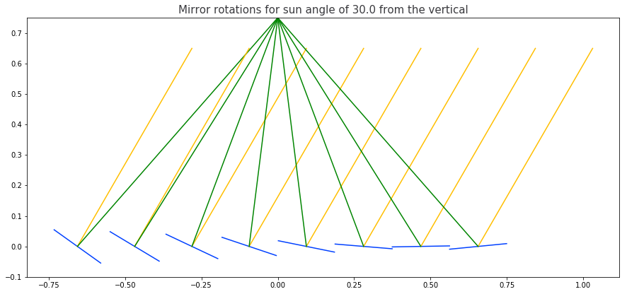
It's going to be simpler during early stages of prototyping if the mirrors all remain pointing towards the same quadrant. Using the Jupyter notebook I found that for an angle change of +/- 20 degrees, for odd values of n (where n is the number of mirror segments), the central 3 mirrors have to change their quadrant and for even values of n, the central 2 mirrors have to change their quadrant. For an angle change of +/- 30 degrees, the central 5 and 4 mirrors respectively have to change their quadrant. Therefore to make early prototyping simplier I could choose a lower range of motion or a larger number of sengments although this would require more parts.
Design to create tomorrow - For now I will try and create a (maybe parametric) design for 8 segment mirror where the central two mirrors are approximated as flat to avoid having to create a separate flexure that can move through the horizontal. In terms of physical width and height of focal point I'll stick somewhere within 0.5 meters for now.
Assuming that I want the mirrors to rotate about their center point then I can either constrain horizontal struts and close and expand the vertical distance, or constrain the vertical struts and close and expand the horizontal distance. However it's proabably going to be easier to keep the either the horizontal or vertical beam completely fixed as opposed to a sliding constraint in which case I'll need to rerun the numbers.
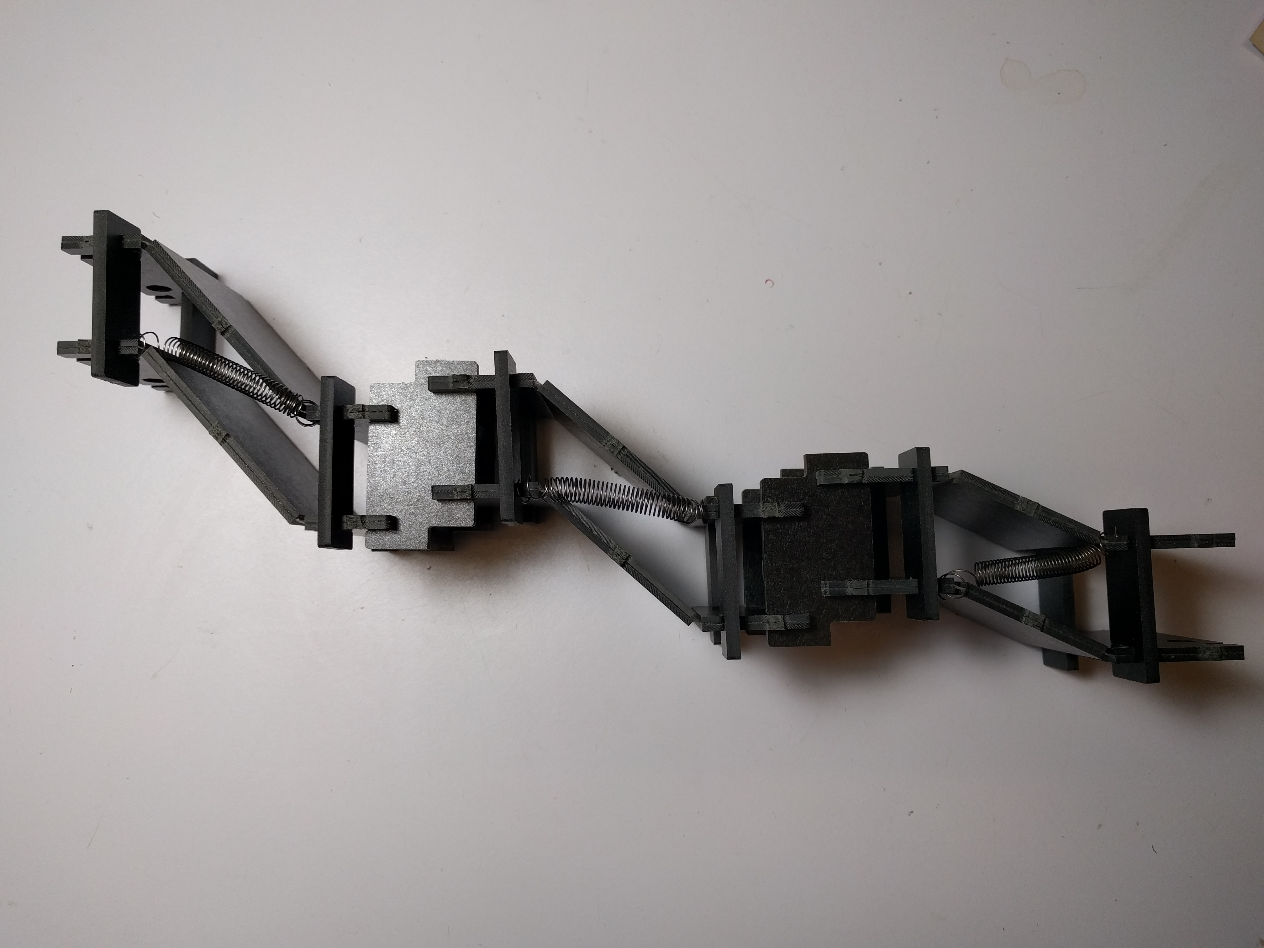
With help from Sam we came up with some ideas for how to implement the angle change. The 4 bar linkage that has featured in mine and Will's work seemed like a good contender so I made a prototype where I picked 3 different central lengths. The springs were necessary to constrain the mechanisms. They weren't included neatly or uniformly in this prototype but give an idea. They could be exchanged for some kind of cross linking flexure, the stiffness of which could more easily be calculated and programmed accordingly. This prototype made me more aware of the need to consider self weight when flexures are concerned.
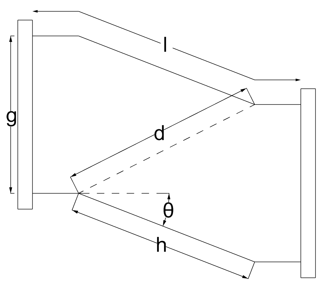
Assuming a spring is connected along $d$, the extension of the spring is found as follows based on a maxiumum and minimum value for theta, $\theta_1$ and $\theta_2$.
$$d^2 = (hcos(\theta))^2 + (g-hsin(\theta))^2$$ $$d^2 = h^2 + g^2 - 2ghsin(\theta)$$The length of d in the two different states are described as $d_1$ and $d_2$
$$d_2 - d_1 = \sqrt{h^2 + g^2 - 2ghsin(\theta_2)} - \sqrt{h^2 + g^2 - 2ghsin(\theta_1)}$$The equation above was solved for h (hinge length) using Sympy by allocating different sets of $[\theta_1,\theta_2]$ and a constant spring extension $d_2 - d_1$. This assumes that the stiffness of the springs is constant in in the horizontal direction despite the fact that they are angled. If this assumption roughly holds then a constant force applied at the root would cause them to displace at equal rates and move between their alloted angle range over the alloted extension $d_2 - d_1$.
However, some of the maths to get here needs to be reworked to account for the fact that mirror surfaces of the serialized 4 bar linkages will undergo horizontal and vertical translations. These translations are stacked up moving from the outside in, so I'll need to figure out a way to account for these and adjust the final angle of rotation accordingly, or simply measure what it is once the angles are measured and figure out what error this introduces.
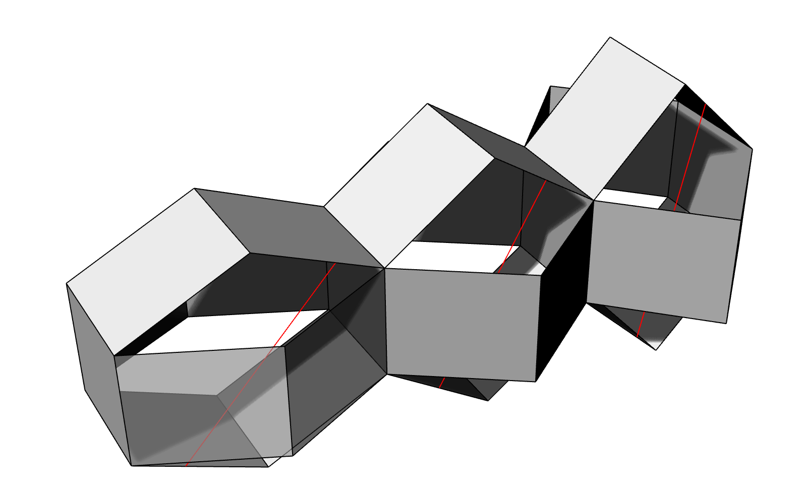
The 4 bar linkage proved to be geometrically challenging to anaylze due to the vertical displacement that occurs in addition to horizontal displacement. Therefore Sam suggested the Sarrus linkage and we worked through the maths to understand how angles and displacements might vary in order to track the sun.
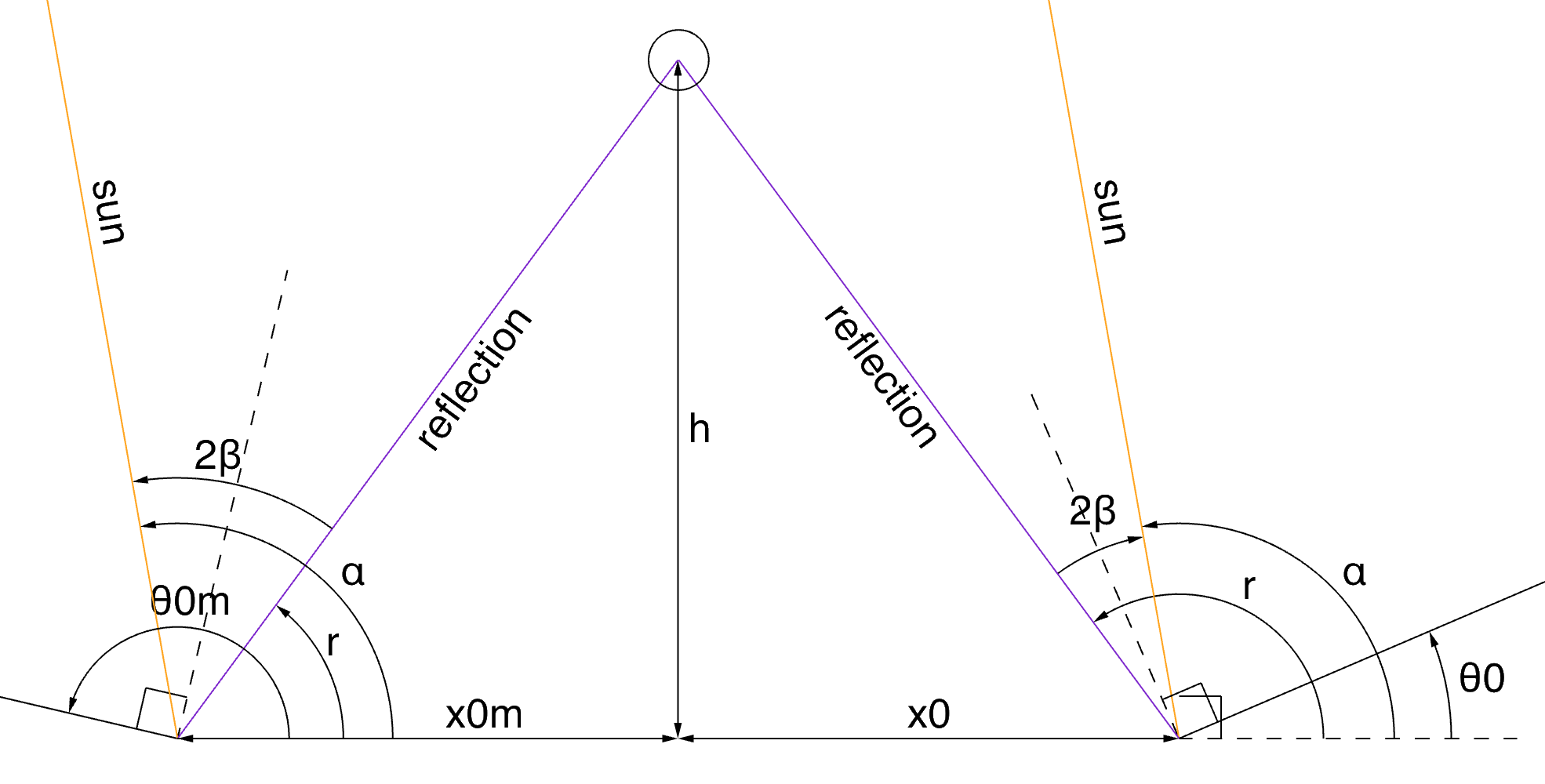
In order to understand this system we need an equation for the angle of inclination of the sarrus linkage given it's displacement. The angle can then be used to calculate the displacement of the base of the next sarrus linkage and recursively you can determine the displacements and angles of all of the linkages. These equations were derived as shown below. In the example 4 sarrus linkages are connected together, each face has equal length, $s$. The focal height, $h$ and the distance to the base of the first mirror, $x_0$ are set as constants. These equations hold for the right side.
$$r = arctan2(h,-x_i)$$ $$2\beta = \alpha - r$$ $$\theta = \alpha - \beta - \pi/2 $$ $$\theta_i = \frac{\alpha - arctan(h,x_i) - \pi}{2}$$ $$x_{i+1} = x_i + 2scos(\theta_i)$$Using the equations above, the following plots show the change in angle and displacement of points $x_i$ for the right half of the mirror as the sun angle changes from -20 degrees to 20 degrees.
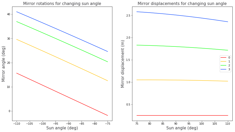
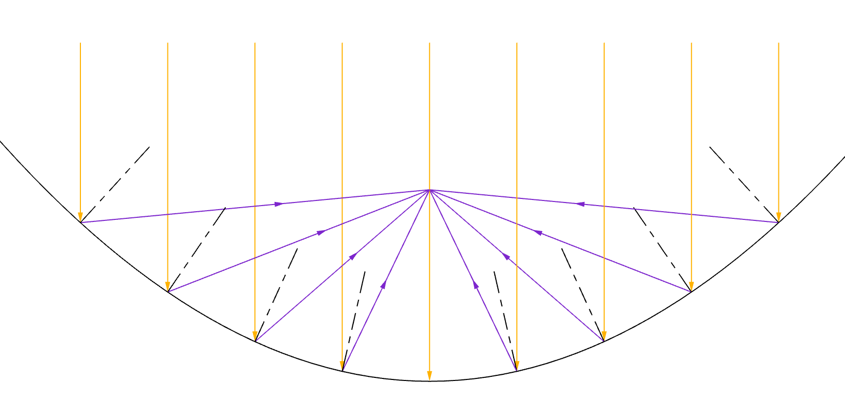
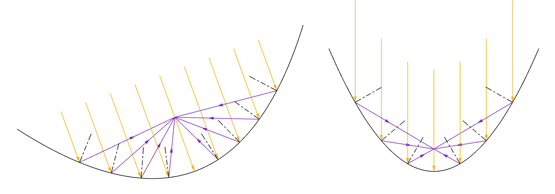
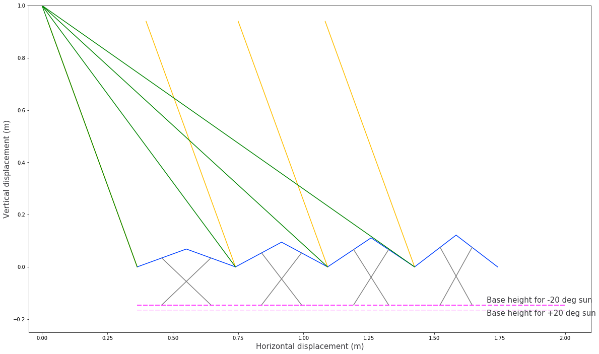
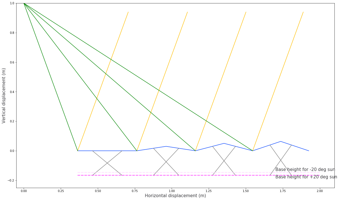
The plots below show how the sarrus linkages (blue) have to deform in order to maintain reflections of the sun's rays (yellow) onto a central concentrator tube (purple).
In the gifs above, the inner mirror takes an inversion at one extreme of the sun's angle. To prevent this the displacement of the first mirror is chosen such that it remains flat for that limit. At this point, the normal points vertically and therefore the angle of reflection equals the angle that the sun makes from the vertical.
$$tan(\alpha) = \frac{x_{0,limit}}{h}$$ $$x_{0,limit} = htan(\alpha)$$
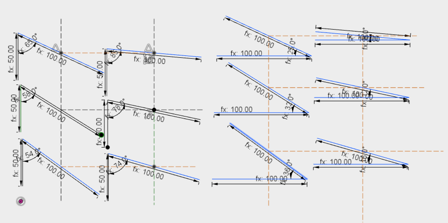
Next I worked out the maths to determine the linkage lengths and attachment points required such that all cross linkages could be deformed by an equal amount vertically and generate the required angle change in each mirror (the extremes of the linkages are shown above for a +/-20 degree sun angle change.
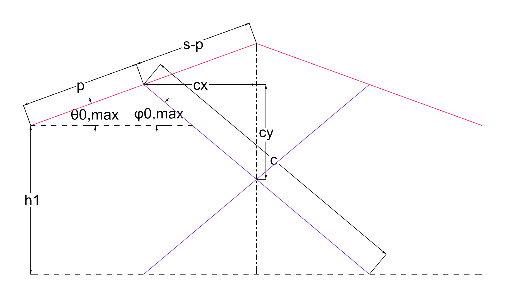
The following equations were used to determine the height change (distance from fixed base of the sarrus linkage to base rail of the cross linkage) $h2-h1$ required to deform a cross linkage with a preset attachment position, $p_0$ and cross linkage length, $c_0$.
$$\frac{c_0}{2}cos\phi_{0,max} = (s-p)cos\theta_{0,max}$$ $$\phi_{0,max} = cos^{-1}(\frac{2(s-p)}{c_0}~cos\theta_{0,max})$$ $$h_1 = c_0sin\phi_{0,max} - psin\theta_{0,max}$$ $$h_2 = c_0sin\phi_{0,min} - psin\theta_{0,min}$$The following equations were then used to determine the attachment position and cross linkage length required to generate the required angle change for the same height change. To do this, Pythagorus' Theorem was used to create quadratic equations in terms of $p$, for $c/2$. Given that $c$ remains constant throughout, the equations for the maximum and minimum angle configurations can be equated and solved for $p$ which in turn can be used to solve for the linkage length, $c$.
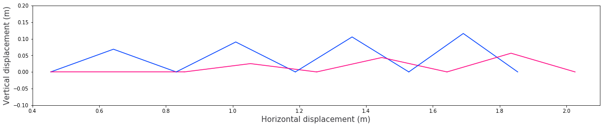
$$cx = (s-p)cos\theta_{i,max}$$ $$2cy = psin\theta_{i,max} + h1$$ $$\frac{c_i}{2}^2 = ((s-p)cos\theta_{i,max})^2 + (psin\theta_{i,max} + h_1)^2$$ $$\frac{c_i}{2}^2 = ((s-p)cos\theta_{i,min})^2 + (psin\theta_{i,min} + h_2)^2$$The image below shows the resulting cross linkages in their maximum and minimum angle configuration. The base points of the sarrus linkages (blue lines) and cross linkages (grey lines) are assumed to be constrained inline, allowed to slide horizontally. Therefore the base of the cross linkages simply needs to be raised in order to deform the linkages by the desired amount. I may need to do some maths to show that the angle change that they create is linear or scales as need to create the required angle change.
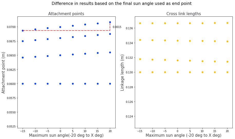
CORRECTION - Having checked my maths for the cross linkage calculations, it turns out solving in this way doesn't hold true for the entire range of motion. I was calculating the linkage lengths and attachment points for the outer linkages based on the height change that results from the first linkage moving from it's maximum to minimum angle. But that incorrectly assumes that the other linkage angles change at the same rate as the first one does. Despite this, having calculated the different linkage lengths and attachment points that result from choosing different end states for the first linkage, it seems as though the results only differ by one or two millimeters and therefore there might be way to design in sufficient elasticitiy into the joints that the mechanism still works.
The graph below shows how different values for the attachment point and cross link length differ based on which two end points are used as the limits of motion. It shows that for the attachment point calculations the greatest difference in the output calculation comes from the 4th sarrus linkage, the difference is just over 1mm, therefore it is hoped that by picking the average value, things might just work out OK.
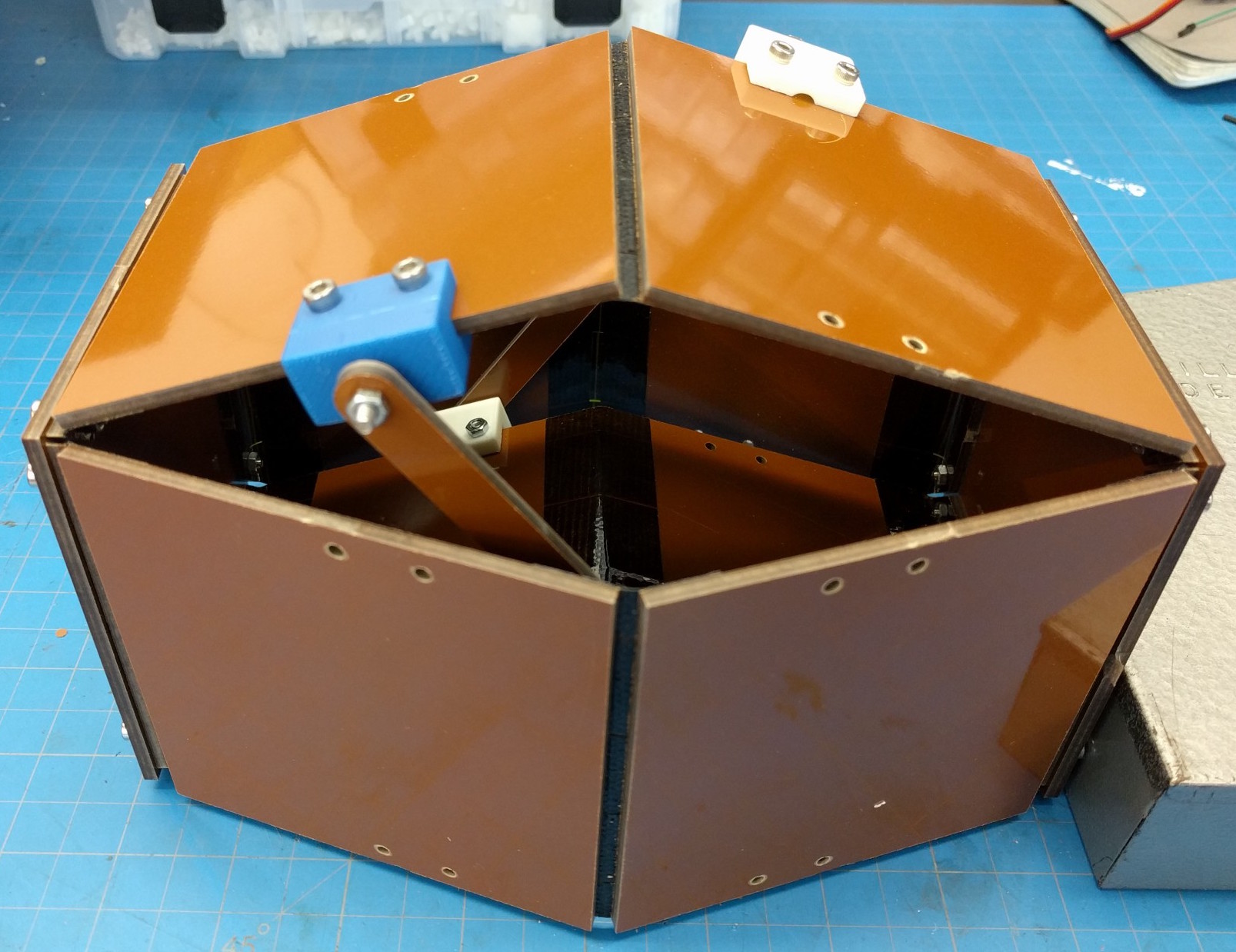
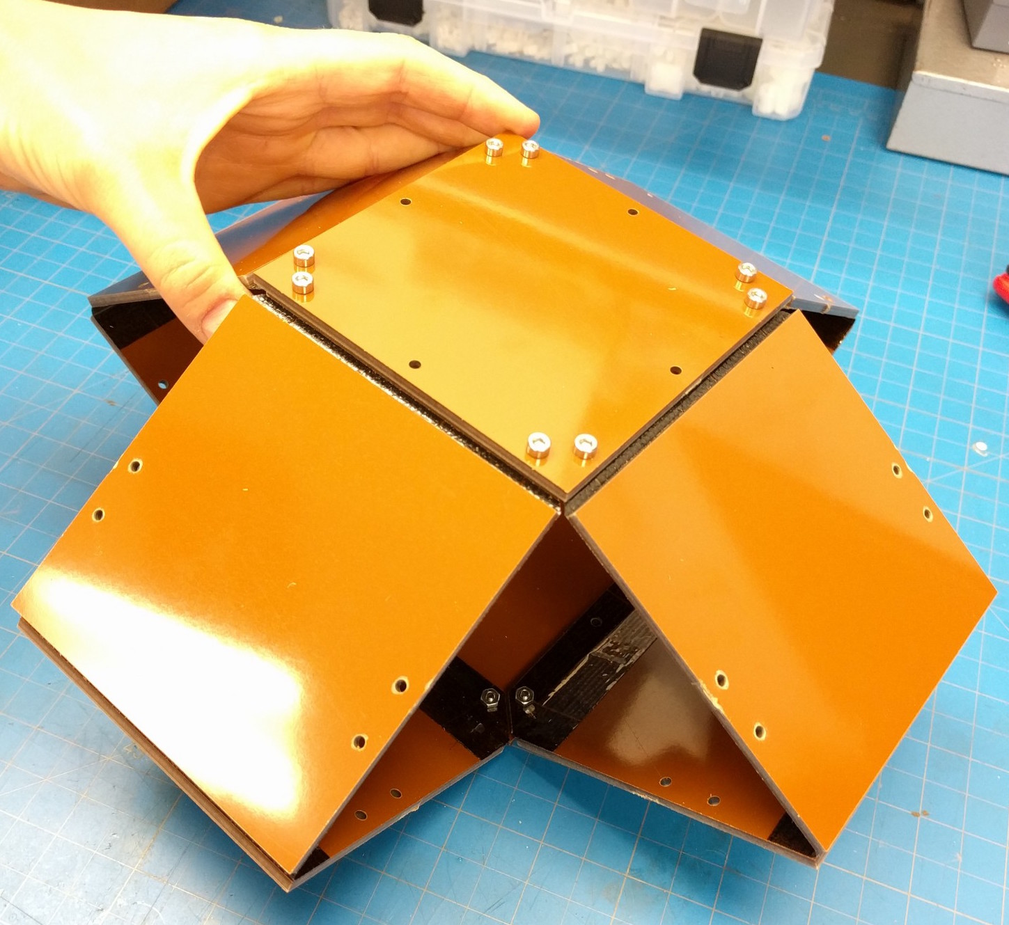
I had a go at prototyping two neighbouring linkages using lasercut Delrin. The bolts weren't evenly tightened and there was some warping in the plastic and generally a bunch of friction which didn't make for a smooth angle change. The geometry has been set up to require the bottom horizontal member to move vertically but remain constrained horizontally. This constraint obviously isn't included in this prototype and there's a question around how difficult it is going to be to include these different constraints without excessive use of bearings or a lot of friction.
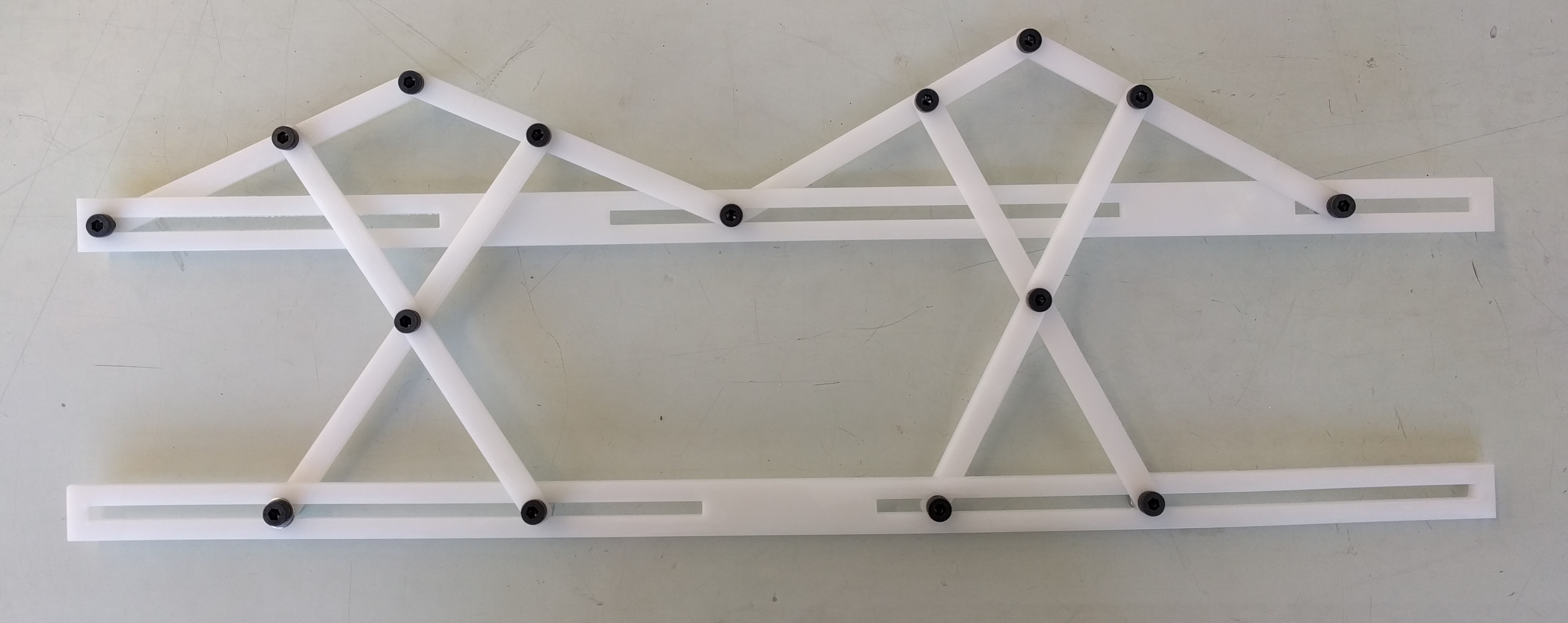
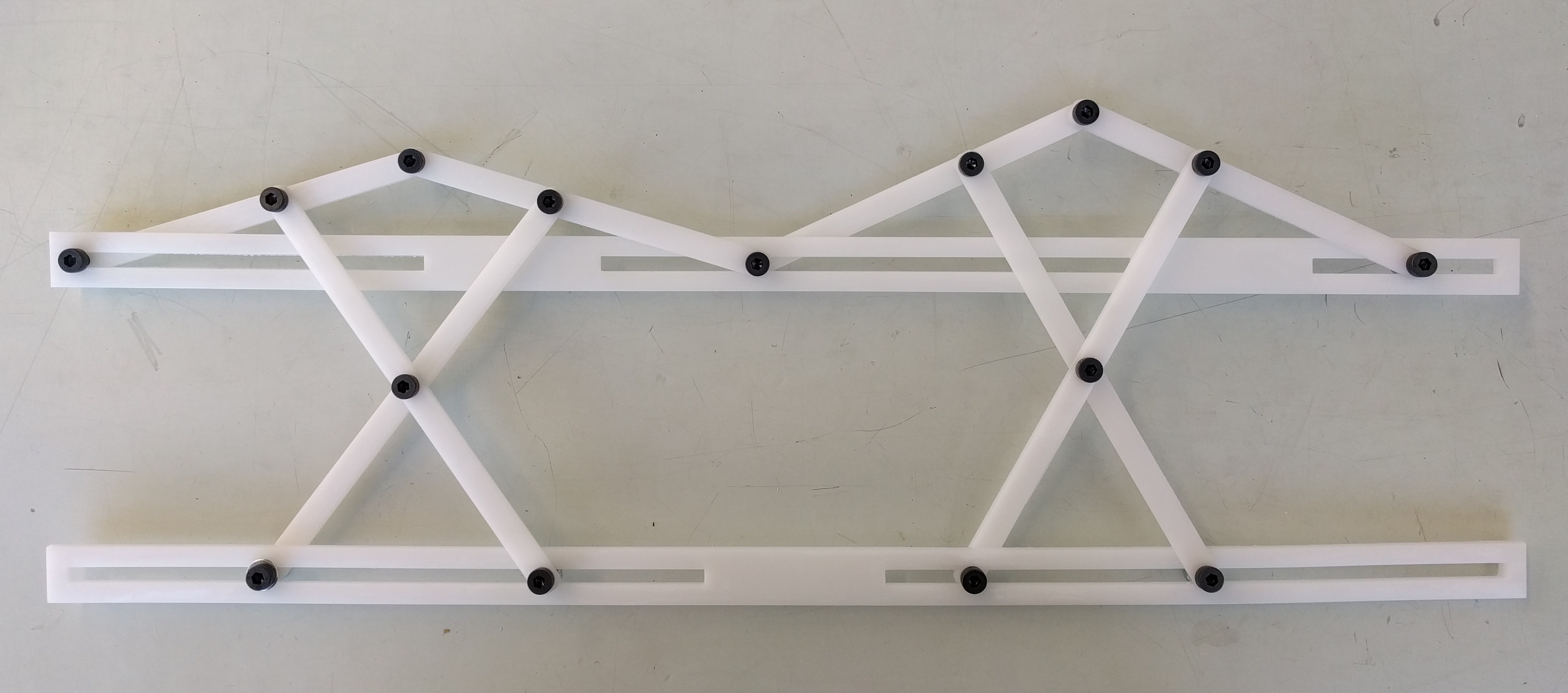
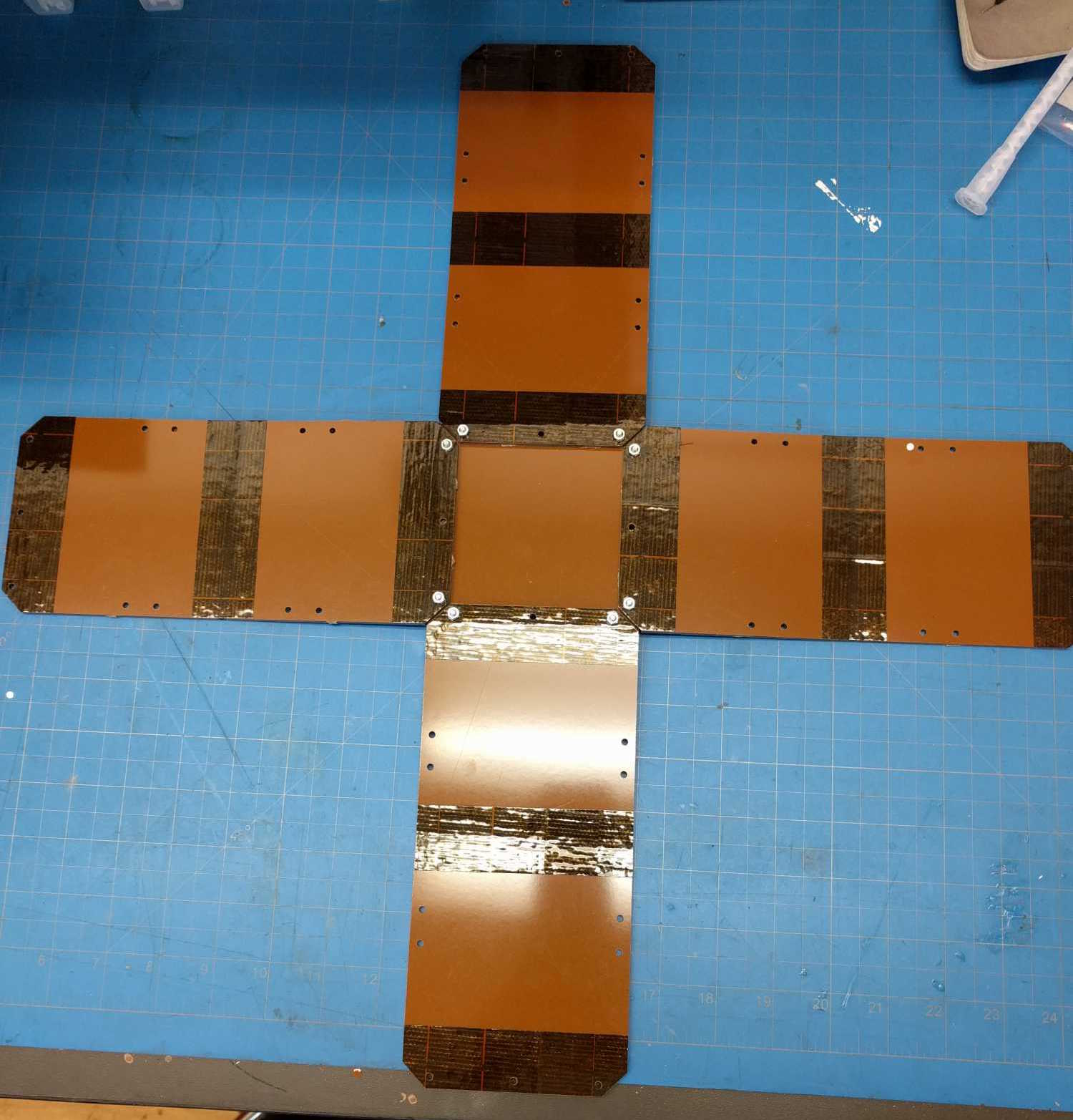
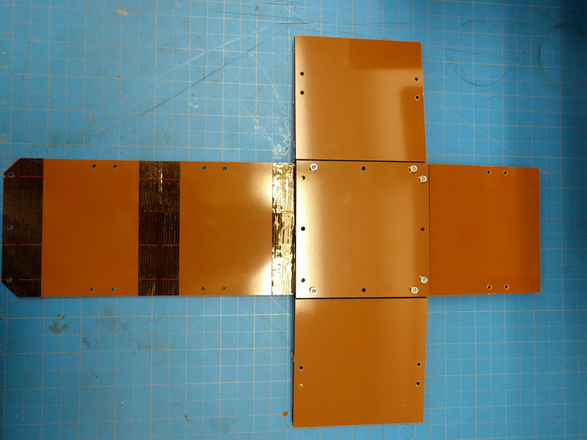
After talking with Sam I realise that the 2D linkage above isn't a fair representation of the sarrus linkage itself and by building the sarrus linkage I should be able to introduce constraints that negate the need for sliding connections.
In building this I realised that the configuration drawn above isn't actually a mechanism. For the maths that I've done I really need the sliding contacts so I really need to rethink this design. I've included images of what I did anyway with the bottom linkage inverted so that it can actually move.
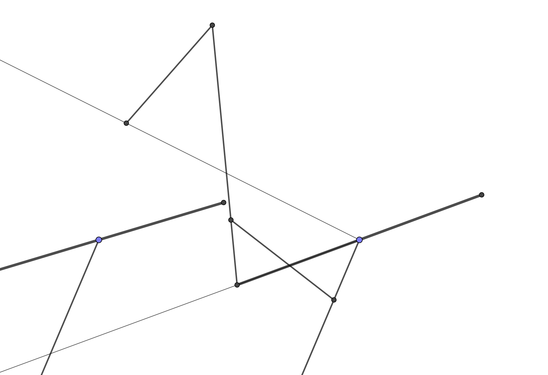
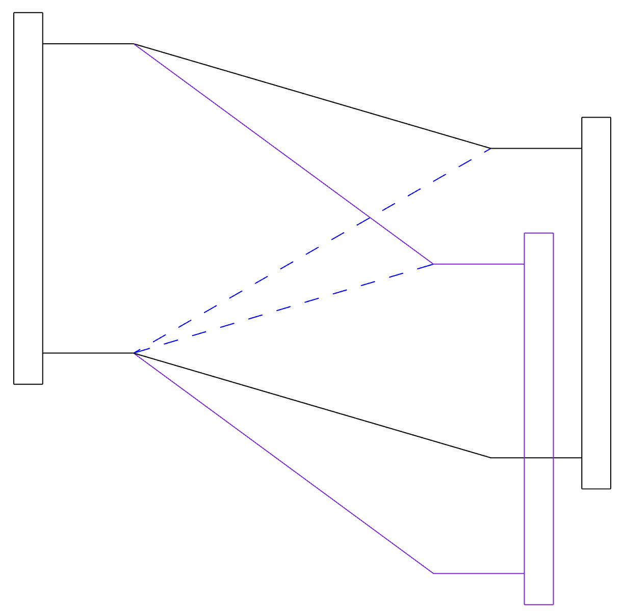
This mechanism would require each mirror being driven by a parallel linkage (shown for the outer left mirror with thin lines). The geometry is possible by using the the property that a parabola is a collection of points from which the distance to a certain point (the focus) is equal to the distance to a line (the directrix). If we therefore specify a focus point and straight line beneath the fresnel lens and include a mechanism to keep the mirror at the bisection of the parallel linkage then we could create a mathematically perfect sun following mechanism.
Phe mirror is constrained to be the bisector of the parallel linkage using a bisector mechanism described here.