The goal of our project was to develop a robust discrete time controller for a magnetic levitation system. In class, we designed a circuit to control a magnetic levitation system in continuous time. For our midterm project we decided to extend our understanding of the differences between discrete and continuous time systems by redesigning the control of the magnetic levitation system using discrete time. From herein, continuous time will be referred to as CT and discrete time as DT.
The CT system utilised an op amp with RC circuit to tune the associated poles and zeros of the system.... We concluded the following transfer functions for the plant and the controller where the controlled took the form of a lead compensator. $${H(s) ={ 1 \over (s+60)({2 \over (s^2-2)})}}$$ $${K(s) ={ s-6.06 \over s-43.8}}$$
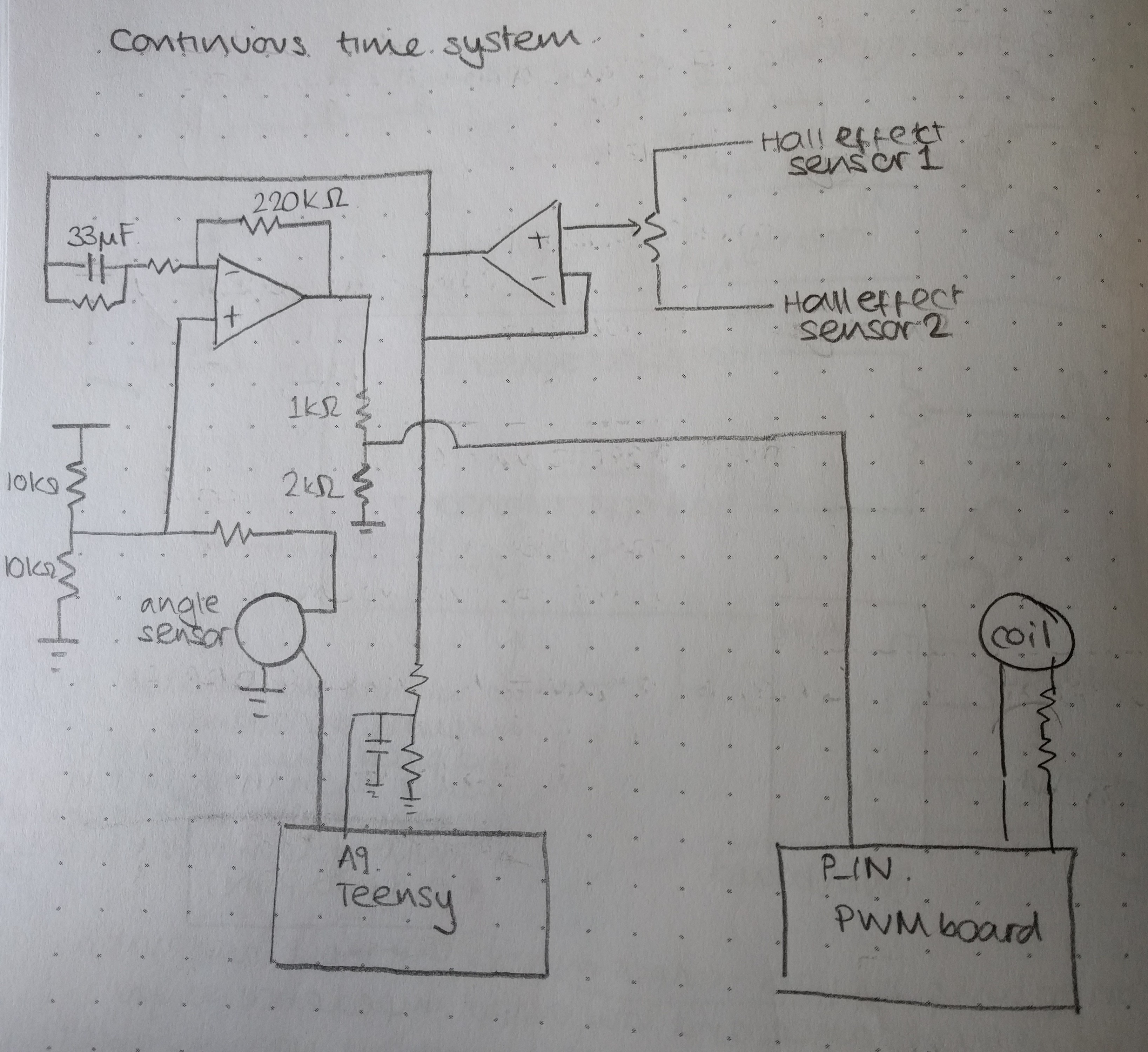
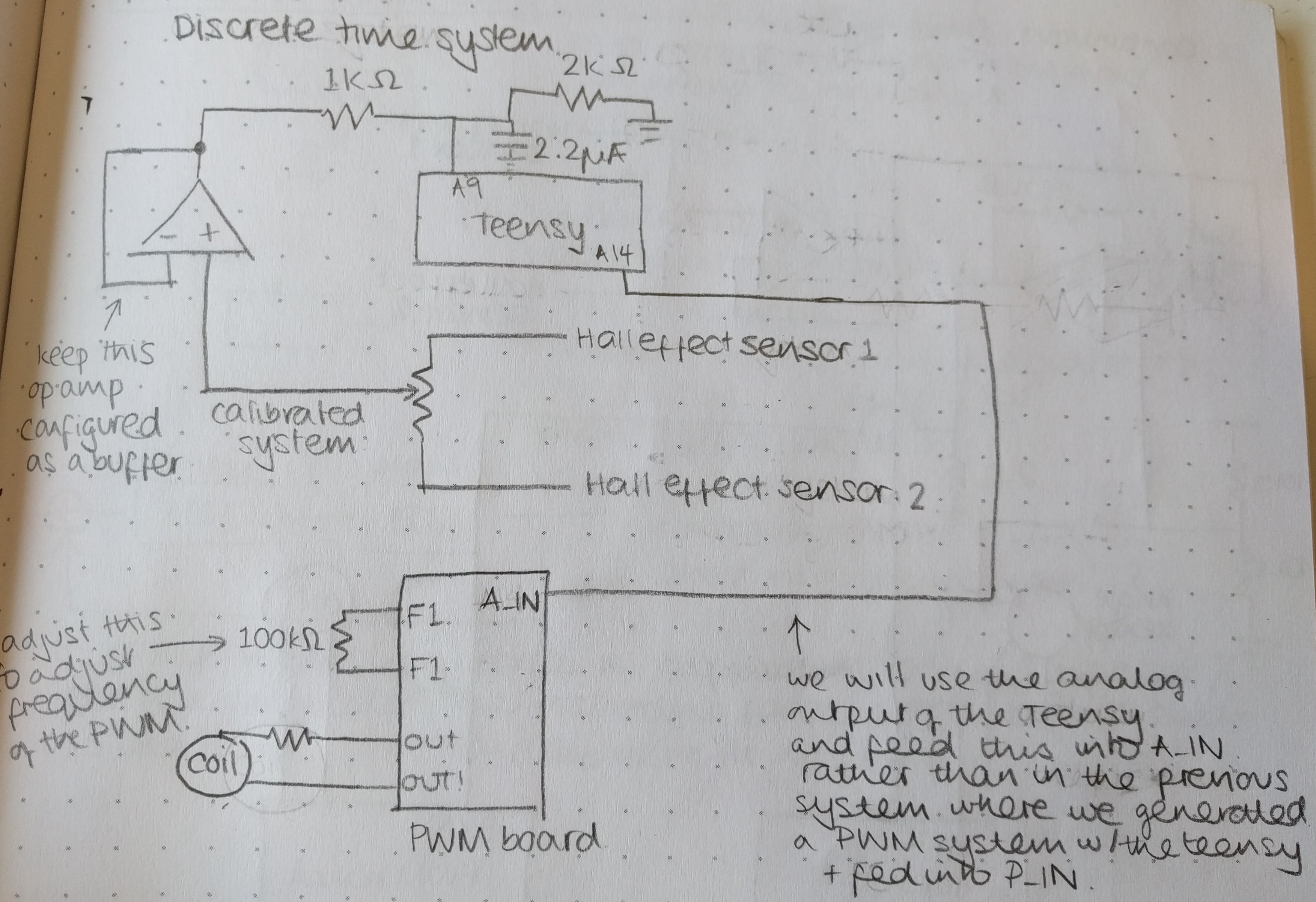
In both the CT and DT circuits, the outputs of the hall effect sensors are connected to a trim potentiometer, used to eliminate any of the effect of coil field variation. The signal is then buffered using an operational amplifier. The output from the potentiometer-buffer stage is treated differently in CT and DT. In CT, the signal passes through an operational-amplifier based lead compensator circuit. The circuit is coarsely tuned using different resistor and capacitor values. Fine tuning is carried out using an angle sensor. In CT the output from the potentiometer-buffer circuit is passed straight to the Teensy which implements Proportional Integral Derivative, (PID) control in software. The circuit is tuned by varying ${K_p}$, ${K_d}$ and ${K_i}$.
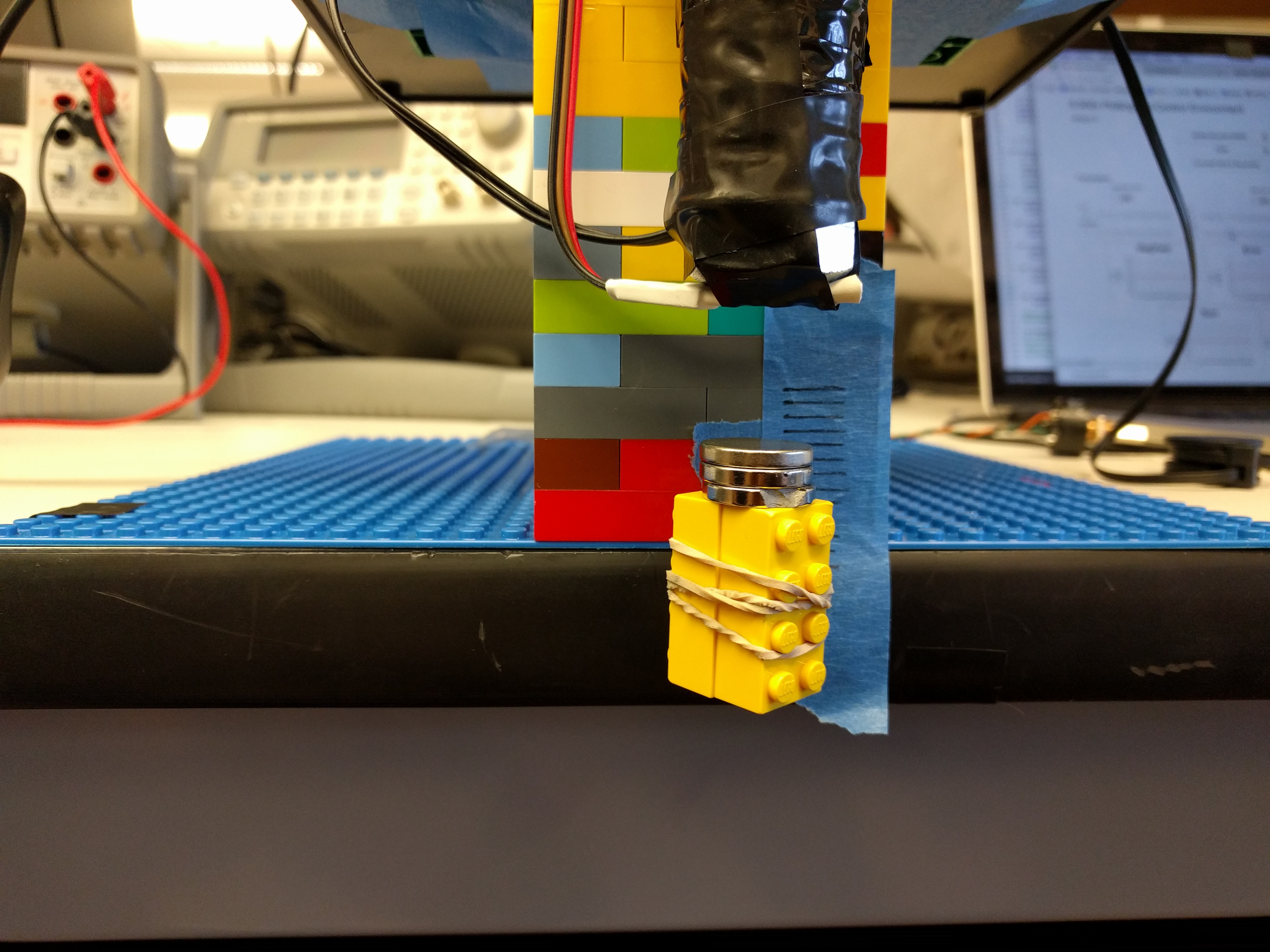
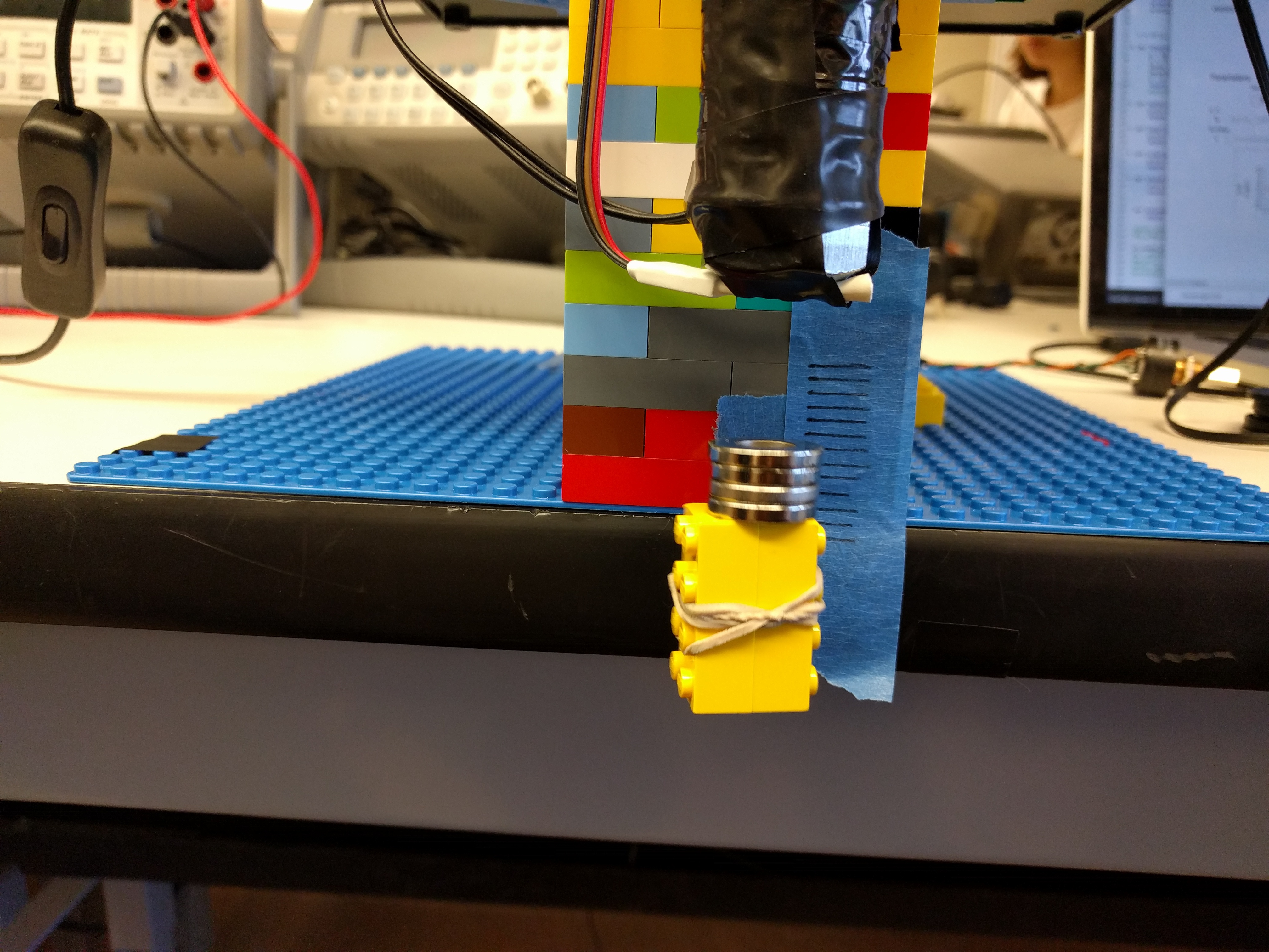
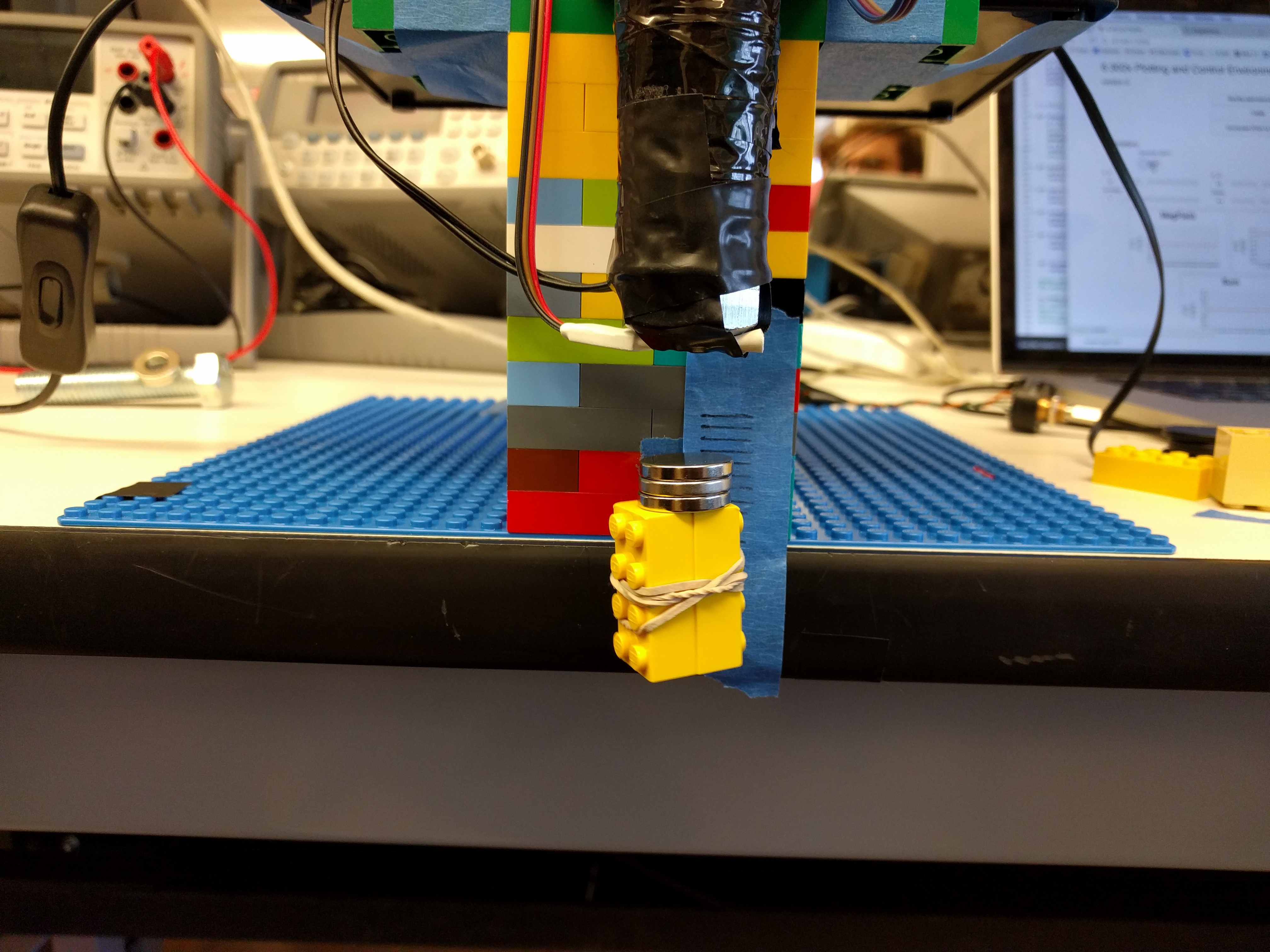
We got the system working with a single magnet using the following settings ${K_p = 44,~K_d = 2.75,~direct=-2.8}$. We used this as a starting point to develop a more robust system, capable of holding a range of weights.
These settings were fairly robust for 2-4 magnets, however for 1 magnet it was fairly unstable and for 5 magnets it was too heavy.
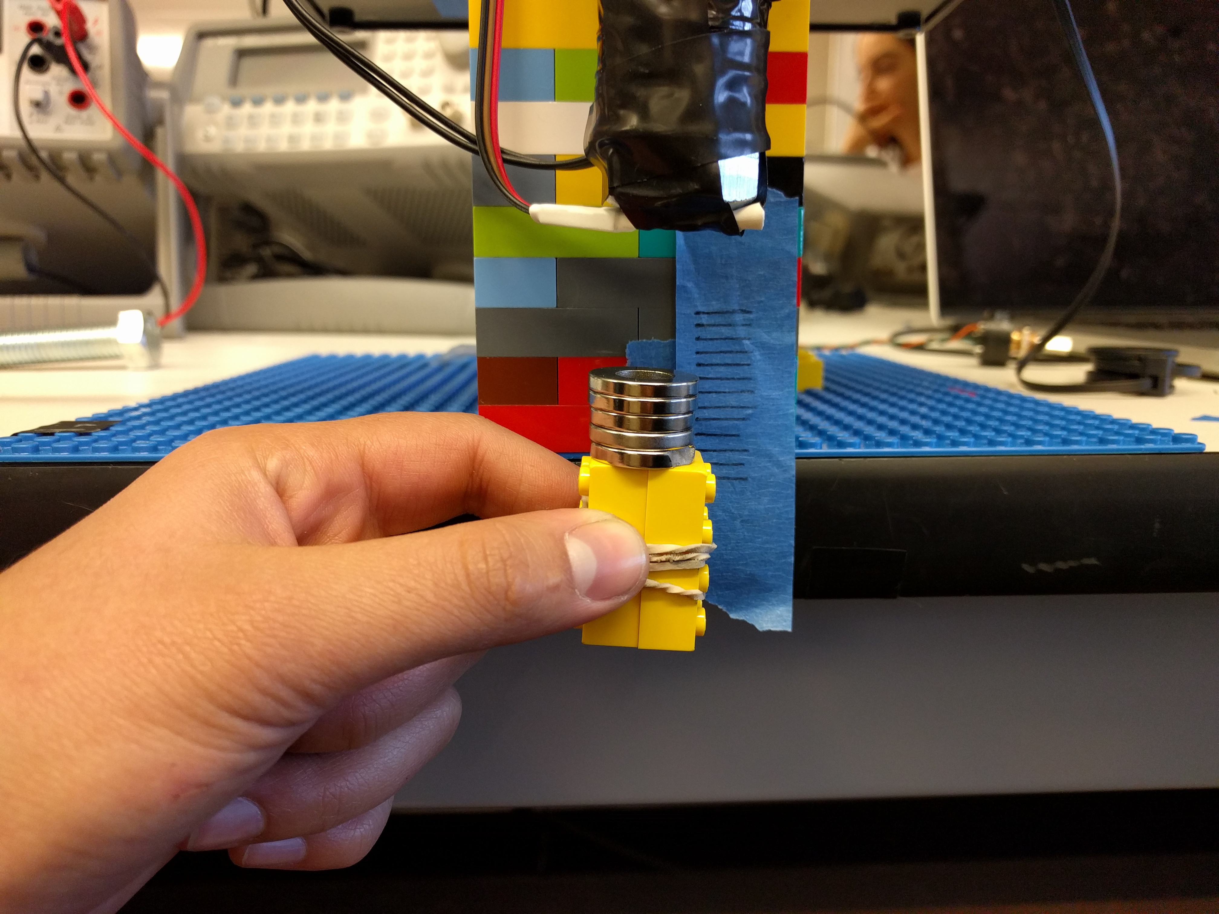
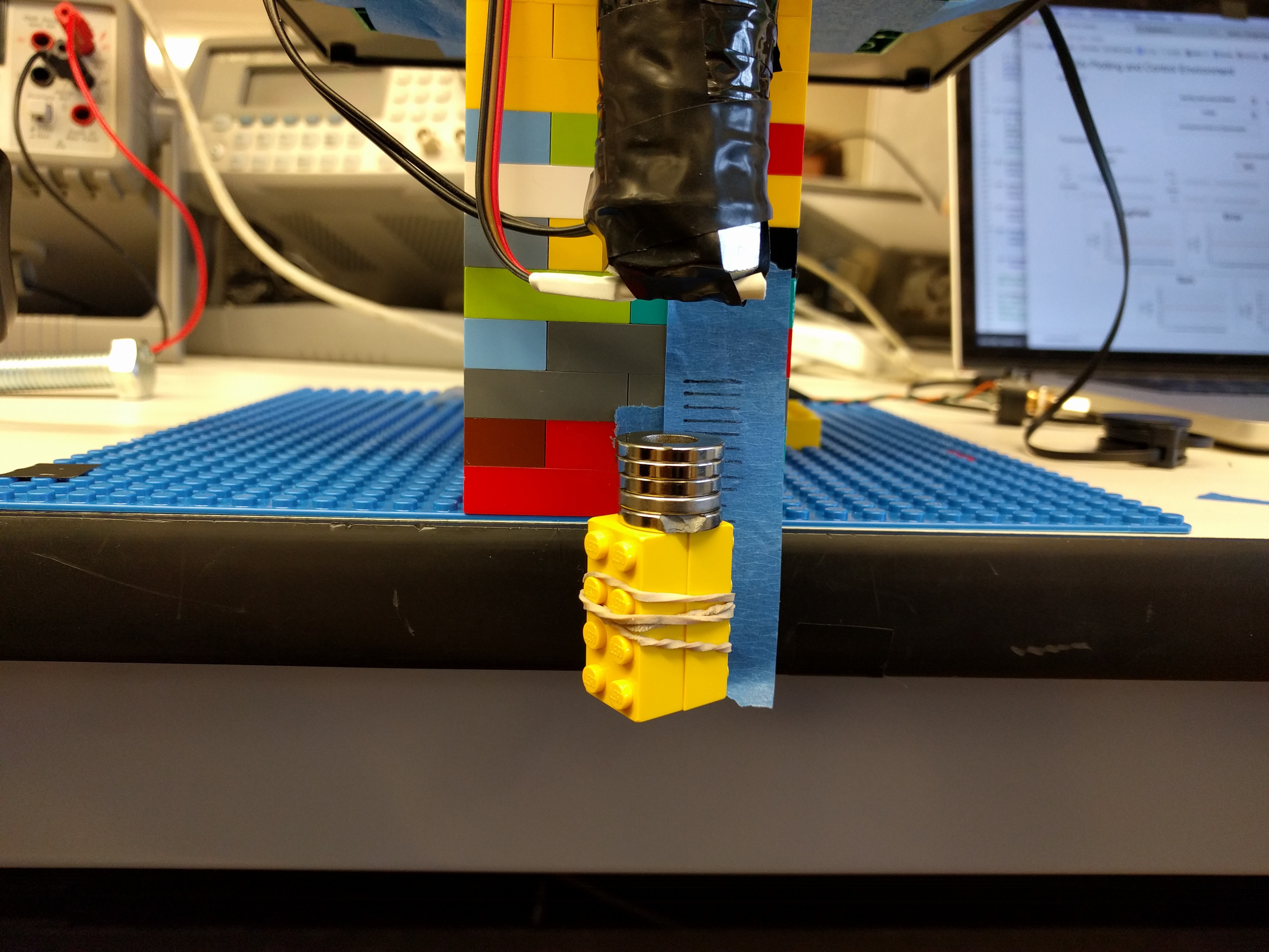
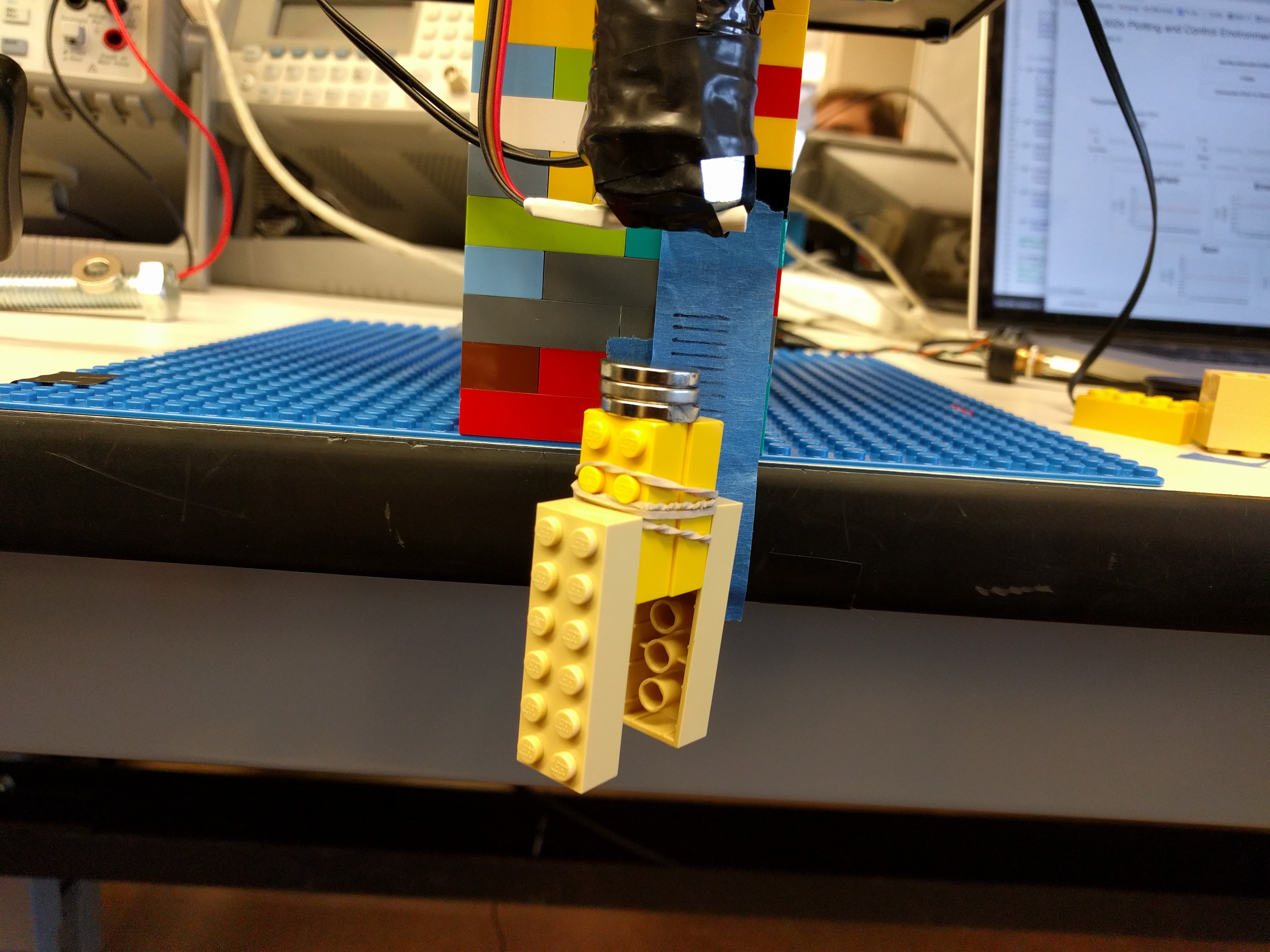
These settings were better at holding heavier masses as shown by the 5 magnet hold. For the case of 3 magnets, we collected error data with and without additional weight, the plots are shown below. The second plot shows that that the heavier system had a smaller error but was more unstable. This indicates that the plant of heavier system has a higher gain. Analytically, as the mass increases the two poles close to the edge of the unit circle move closed together. If, after making this change to the mass you increased the DC gain to compensate for it, then you would create an overall more stable system.
![]()
![]()
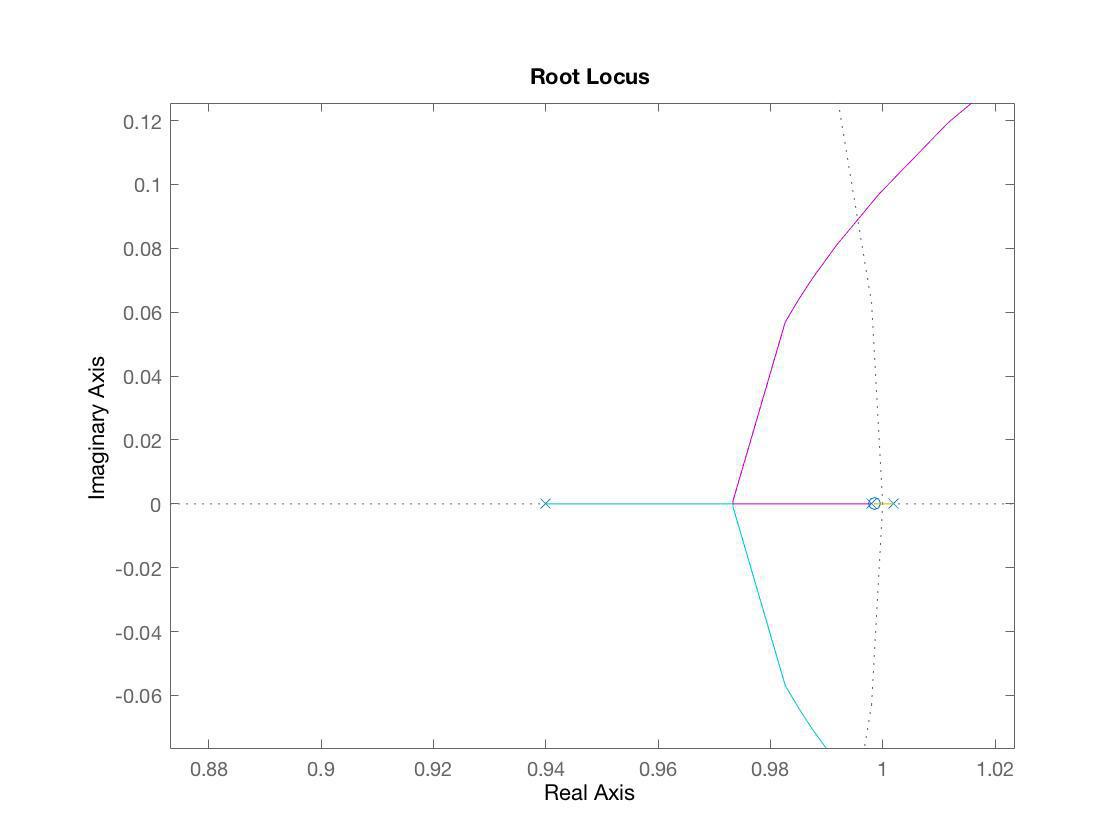
We started to develop a model of the system. Below is the transfer function of the continuous time system converted into discrete time where one of the three poles is unstable. The root locus for this approximated plant shows that it quickly becomes unstable with increasing gain.
$${H(z) = {1 \over (z-0.94)} ~ {dt^2 \over (z-0.998)(z-1.002)}}$$ $${K(z) = K_p + {K_d(1-{1 \over z^m}) \over dt }}$$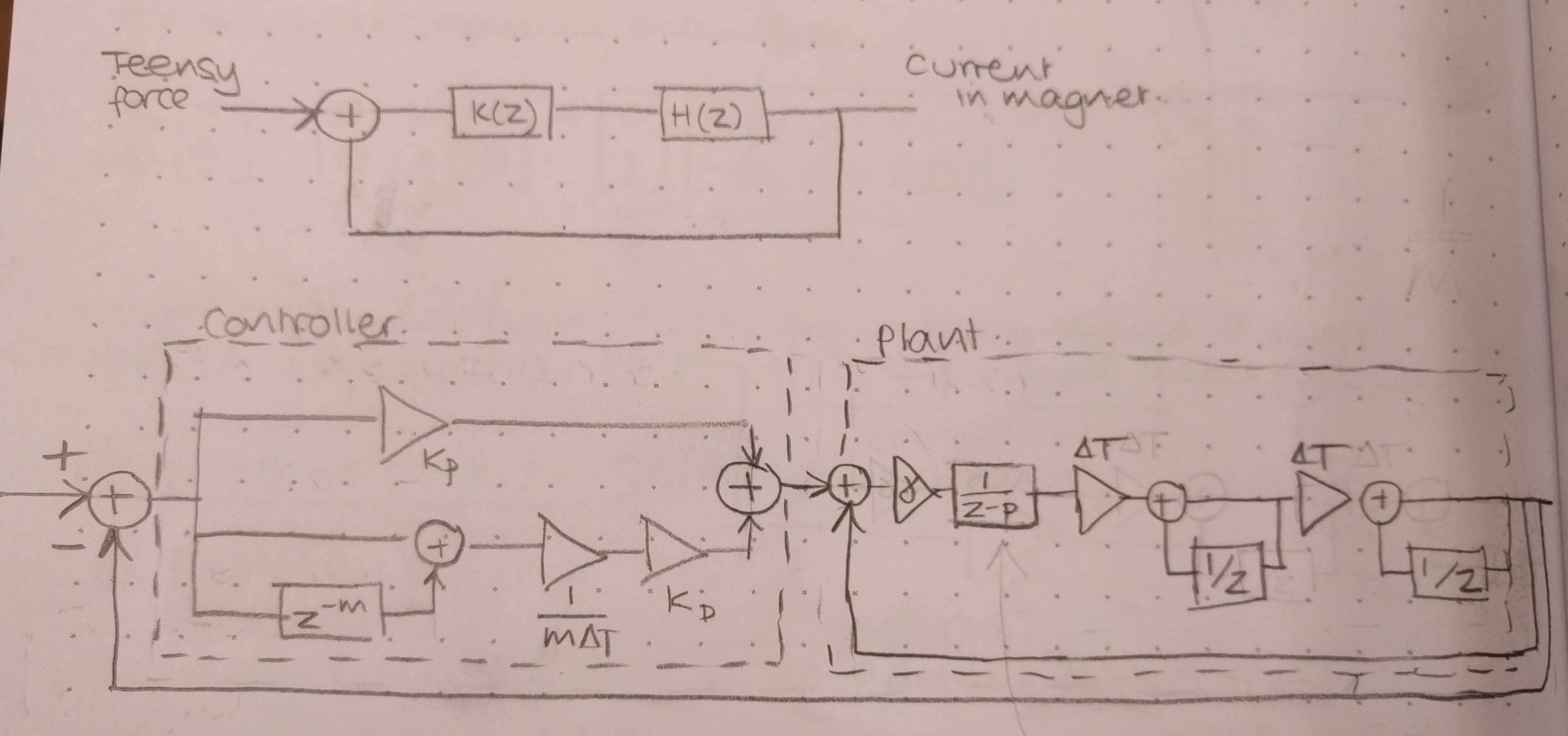
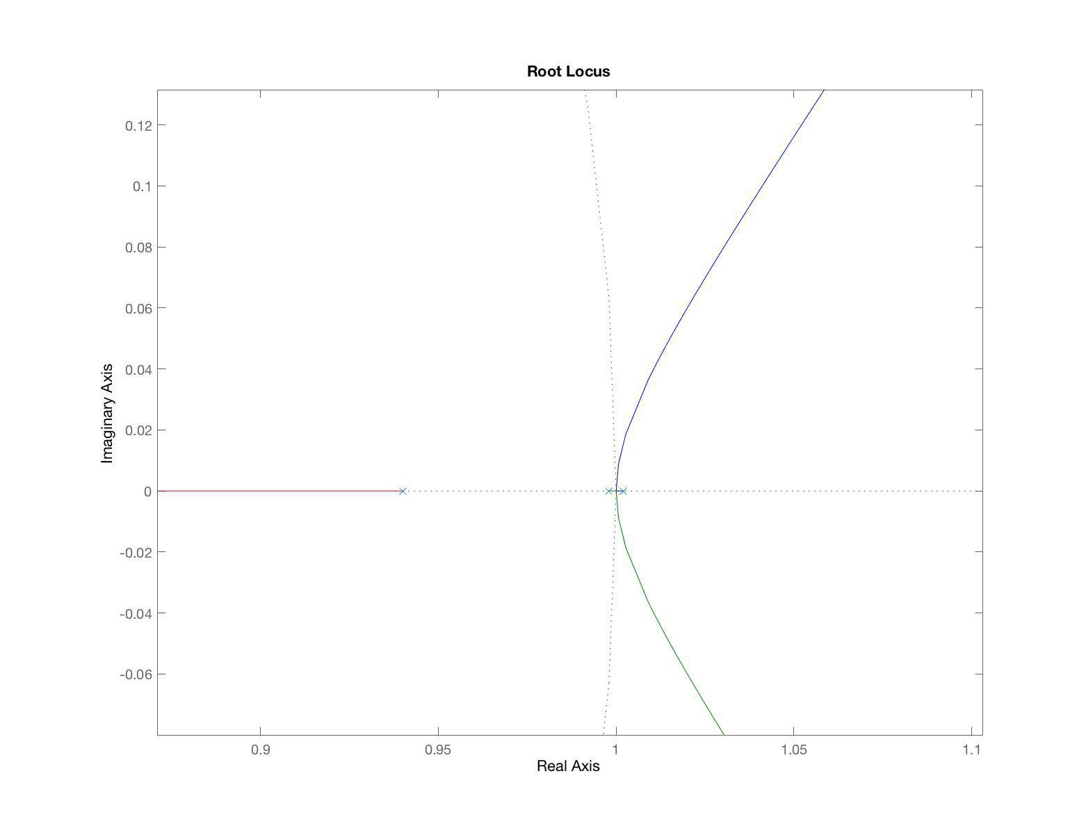
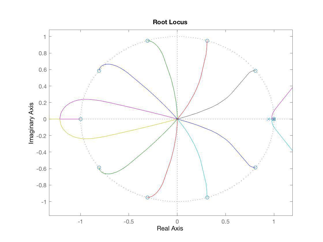
The root locus of the plant and the controller confirm that the system becomes stable. Figure 6 shows the region around one on the Real axis with the. Figure 7 shows the full plot where there are 10 poles as a result of the m value.
In conclusion, we successfully designed and implemented a feedback control system to levitate a range of magnets and weights in discrete time. Based on discussion during our check off, one reasonable method for creating a more robust system would be to work from a current stable state and change the gains until instability occurs.