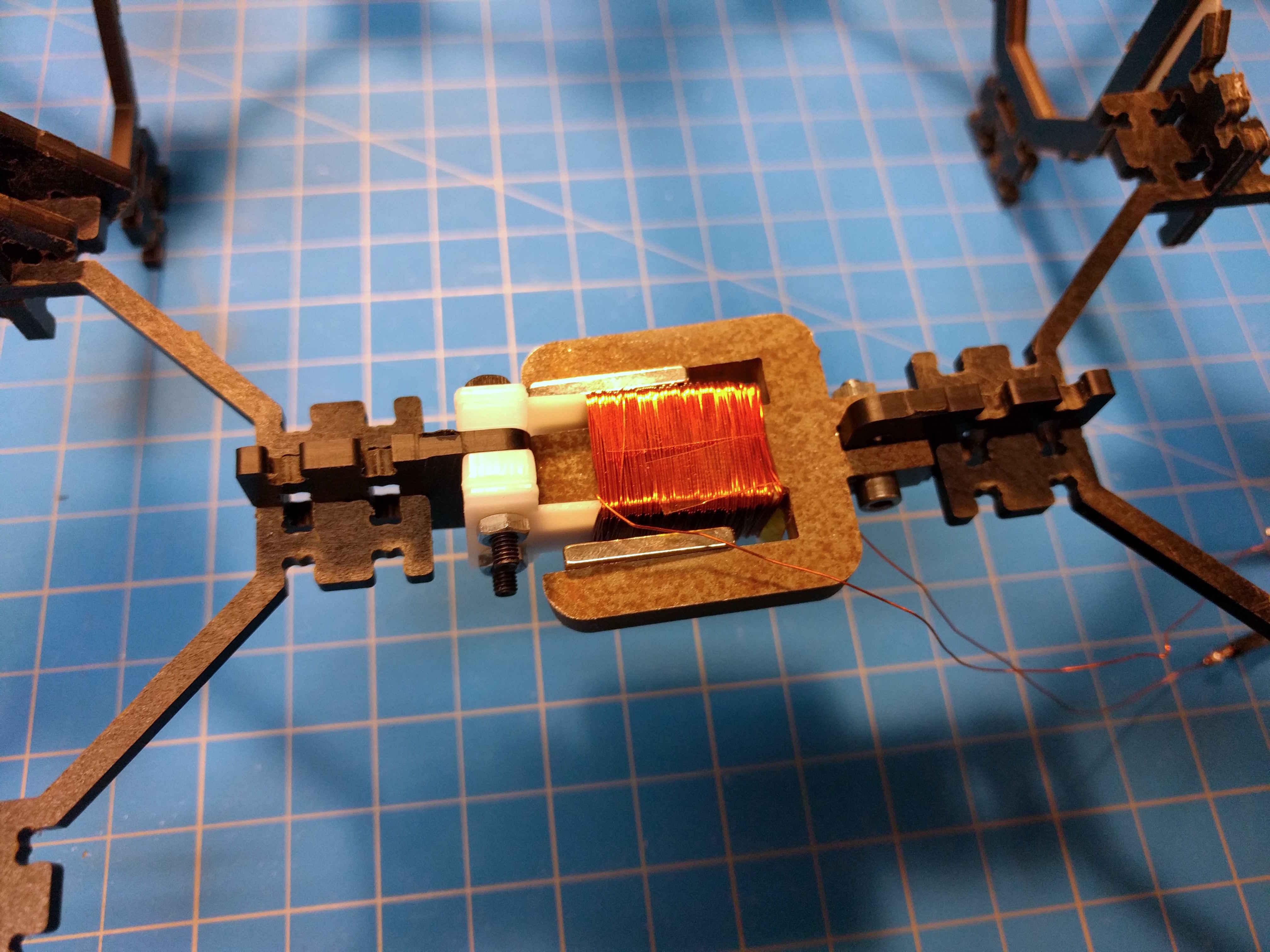
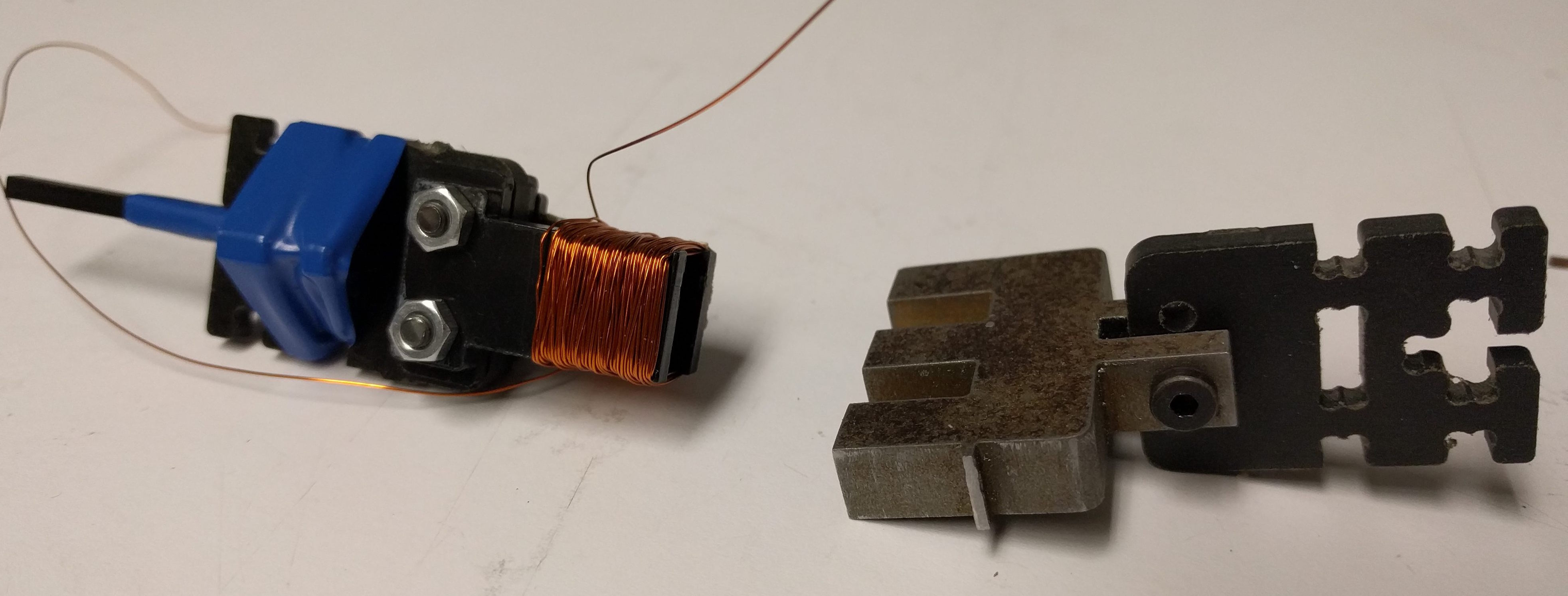
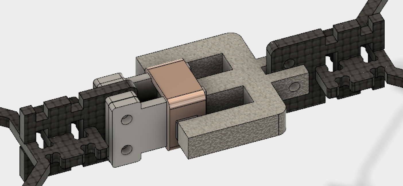
The first version of the actuator is a linear voice coil actuator.
Using steel 0.28" = 7.2mm thick. The kerf of the waterjet resulted in a 7mm feature measuring 6.9mm on the underside of the component. The first version was assembled by Harith.
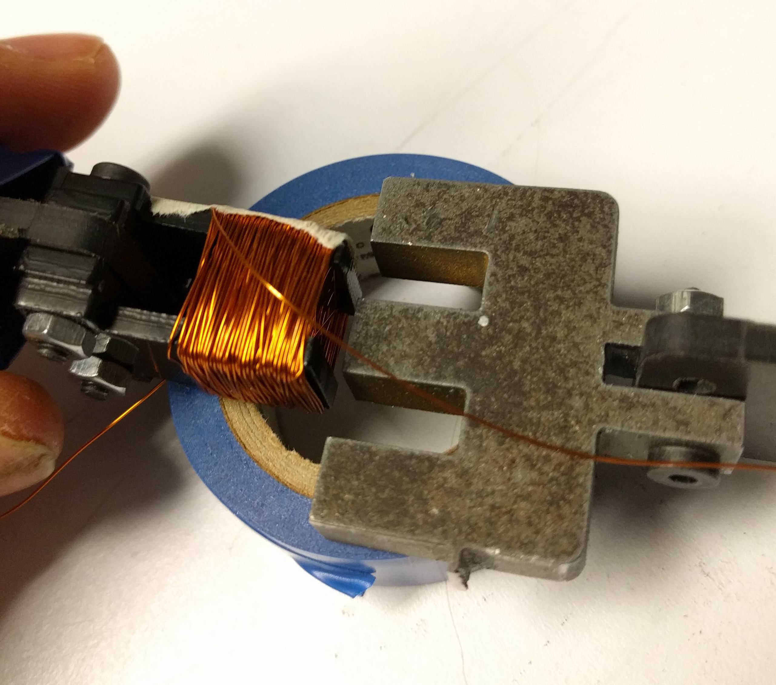
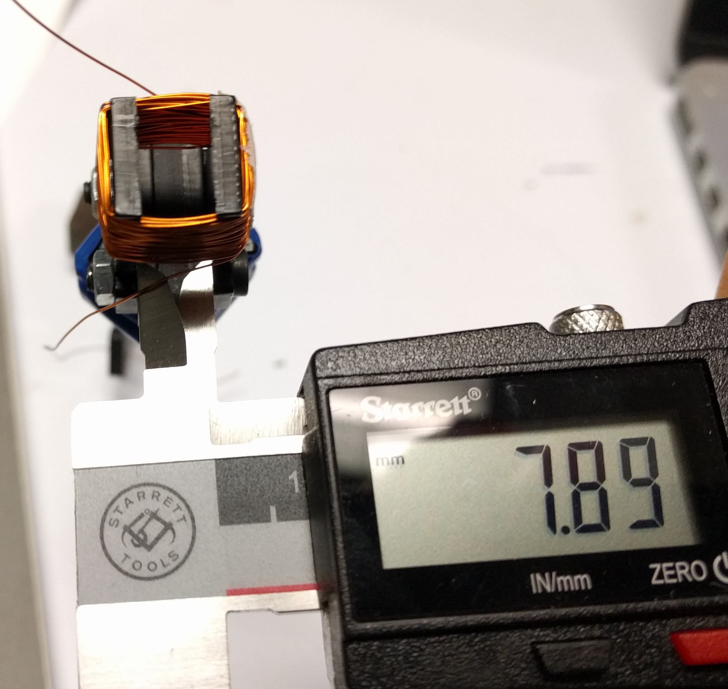
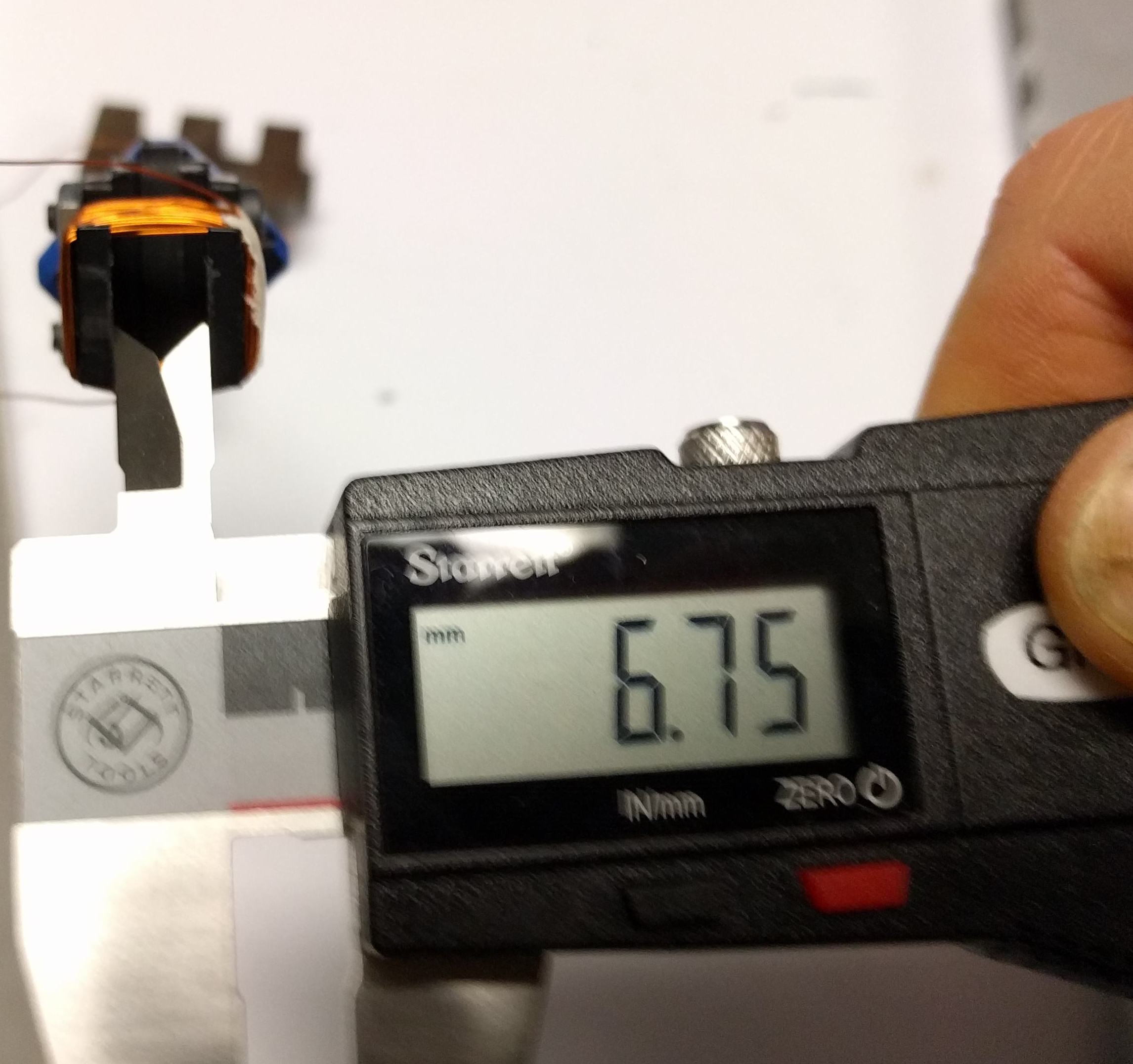
Two 3/32" Delrin cantilevered pieces were used to create a form to wrap the coil around. This design didn't prove stiff enough, shown by the measurements below. The dimension at the end of the coil is less than the dimension of the flux guide. To overcome this we could add another spacer or add reinforcement to make the form a rectangular cylinder as opposed to cantilevered pieces.
I began by driving the coil with 10-12V, this resulted in vibrations soon after power on. Turning down the power to ~6V removed the vibrations. Also, it's better to power these coils using current control rather than voltage control given that current is what dictates the flux and forces generated.
Despite the vibration I tested a few different flux guides of varying lengths. The two videos show that the location of the magnets in reference to the coil is important, after speaking with Will I've learned that the actual length of the flux guide doesn't matter too much, it's analagous to adding extra wire in a circuit. In this siutation then, the varying lengths of flux guide change where the magnet is located within the electromagnetic field which changes the way in which the force acts on it.
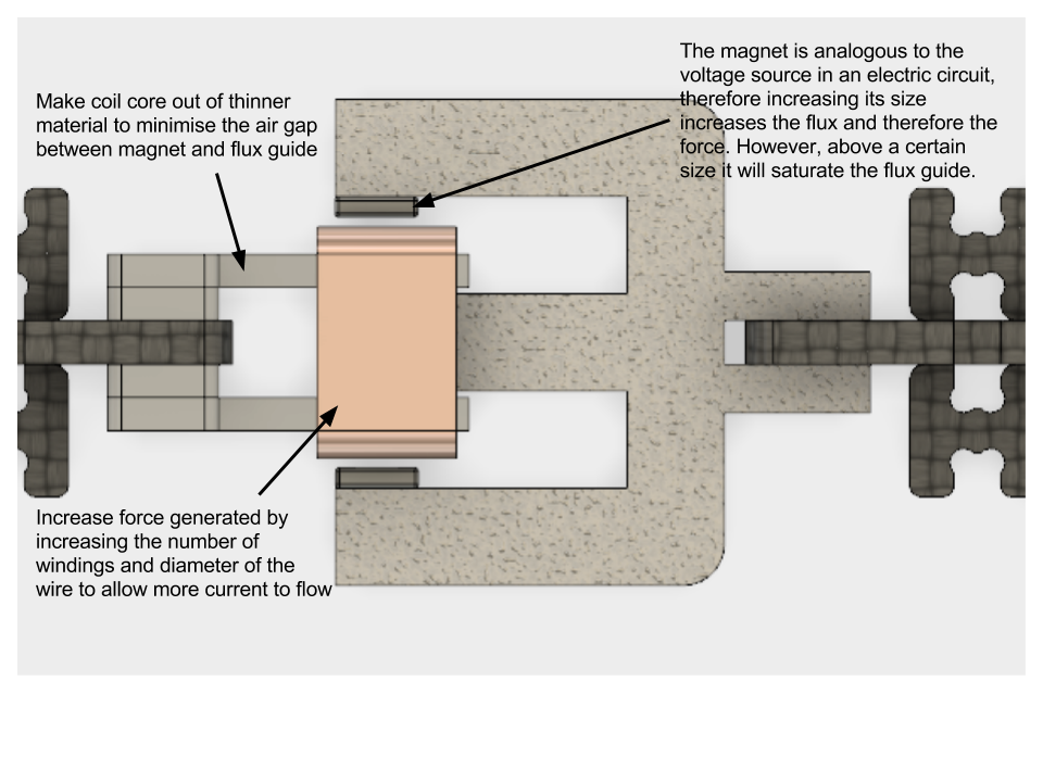
Design modifications required to make assembly easier/better:
Design modifications required get higher force generation:
Neil's class Physics of Information Technology has three parts that cover the relevant theory including fields and waves, circuits, waves guides and waveguides and magnetic materials and devices.
Rough calculations were carried out using magnetic circuit theory to find the magnetic field across the coil and calculate the the resulting Lorentz force.
$$F = force~(Newtons,N)~~~B = magnetic~field~intensity~(Tesla,T)~~~I = current~(Amps,A)~~~L = length~of~conductor~(Meters, m)$$ $$For~a~coil~L=Nr~where~N=number~of~turns~and~r=coil~radius~(Meters,m)$$ $$F = BIL$$ $$F = BINr$$ $$F = 0.2*0.5*100*0.003 = 30mN$$This force is incredibly small and whilst the value for B is pretty inaccurate it helps to give an idea for how the various parameters of the design contribute to the overall force generated. I'm also interested in how the parameters impact the distance travelled but for now I will focus on the magnitude of the force.
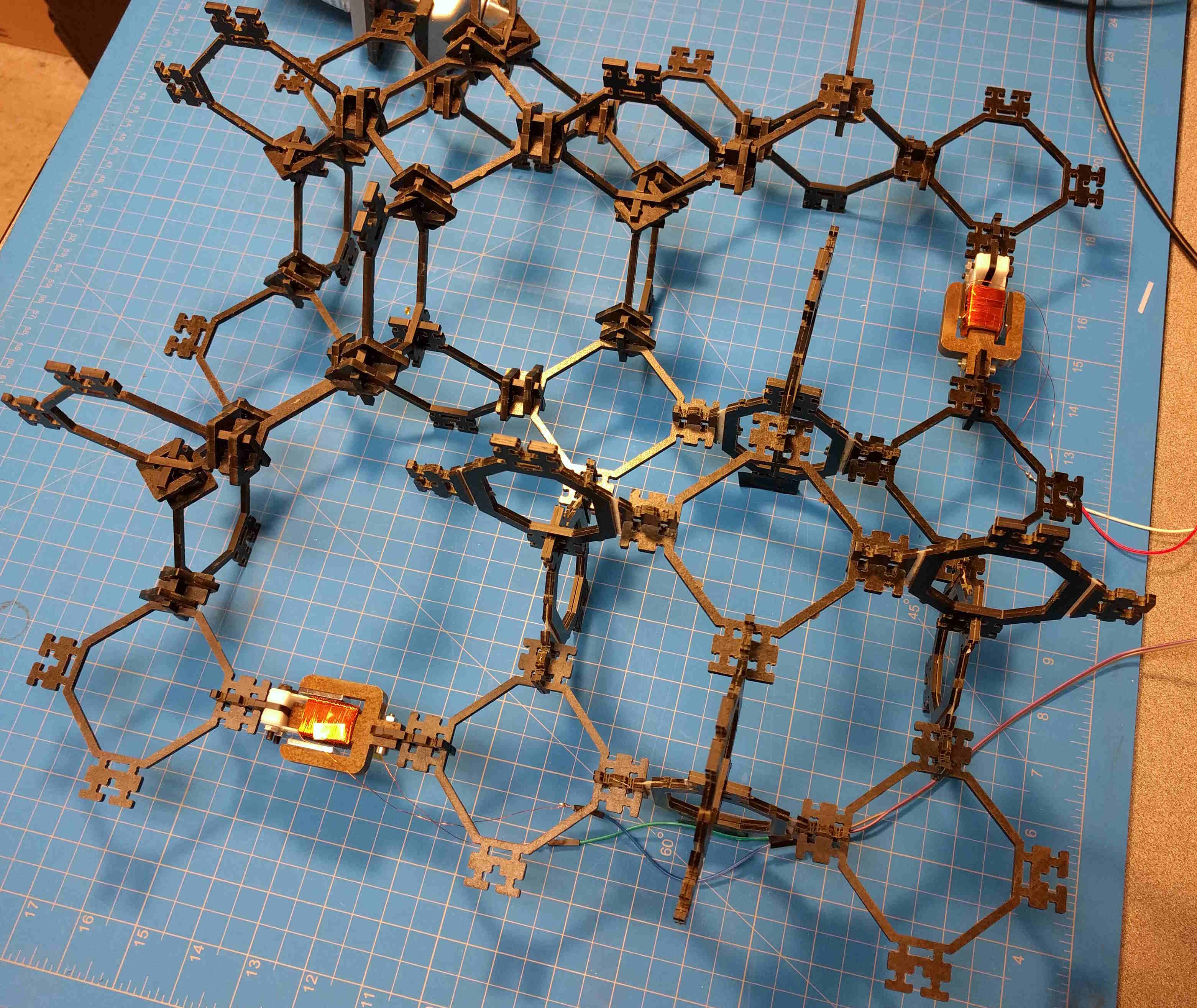
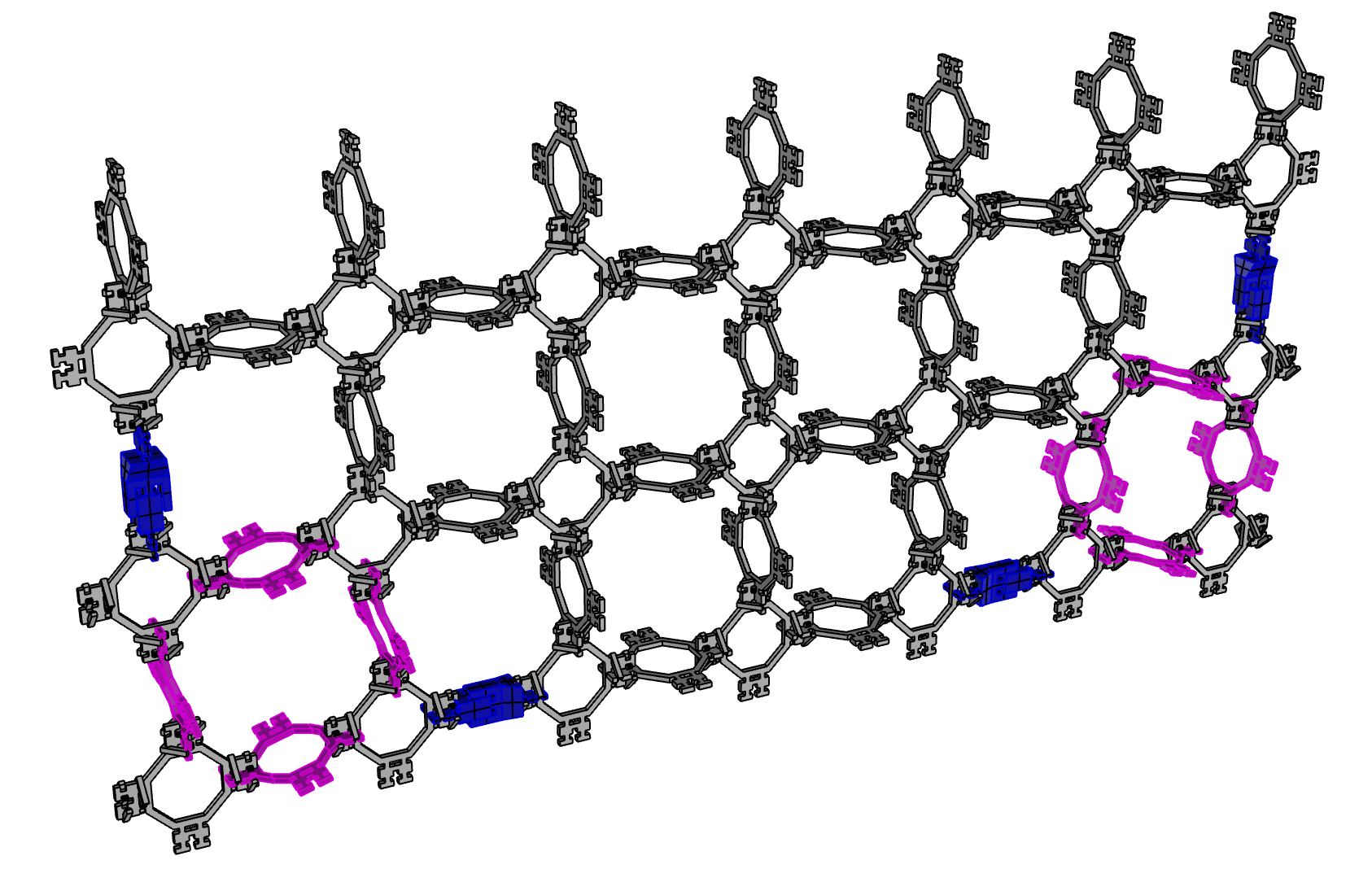
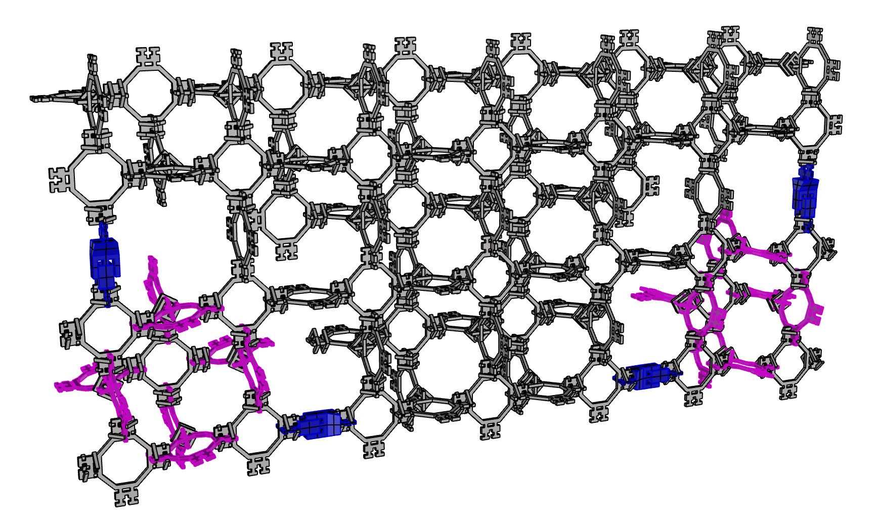
As a means of qualification, I need to calculate a charactistic force required of the actuation part type. An earlier example system is shown below. At the current scale using the current design, each square part weighs 6.7 grams and each clip weights 1.1 grams. Assuming an average of 4 clips to every square piece gives a unit mass of 11.1 grams. The two images demonstrate how the layers would stack up. The two layer assembly contains ~100 of the square parts and 4 motors. Therefore each motor needs to be capable of moving ~25 parts = 11.1 grams * 25 = 278 grams which requires roughly 2.7N to lift. Therefore, this will be a target force in the next revision of design.
I started by looking at an example that Will had created. I then ran through an example for analysis of a 2D rotating generator and a one-sided generator and plate, (be sure to download the correct version of the tutorial for your version of COMSOL, I'm using 5.3 NOT 5.3a).
By means of an introduction to those who are new to COMSOL:
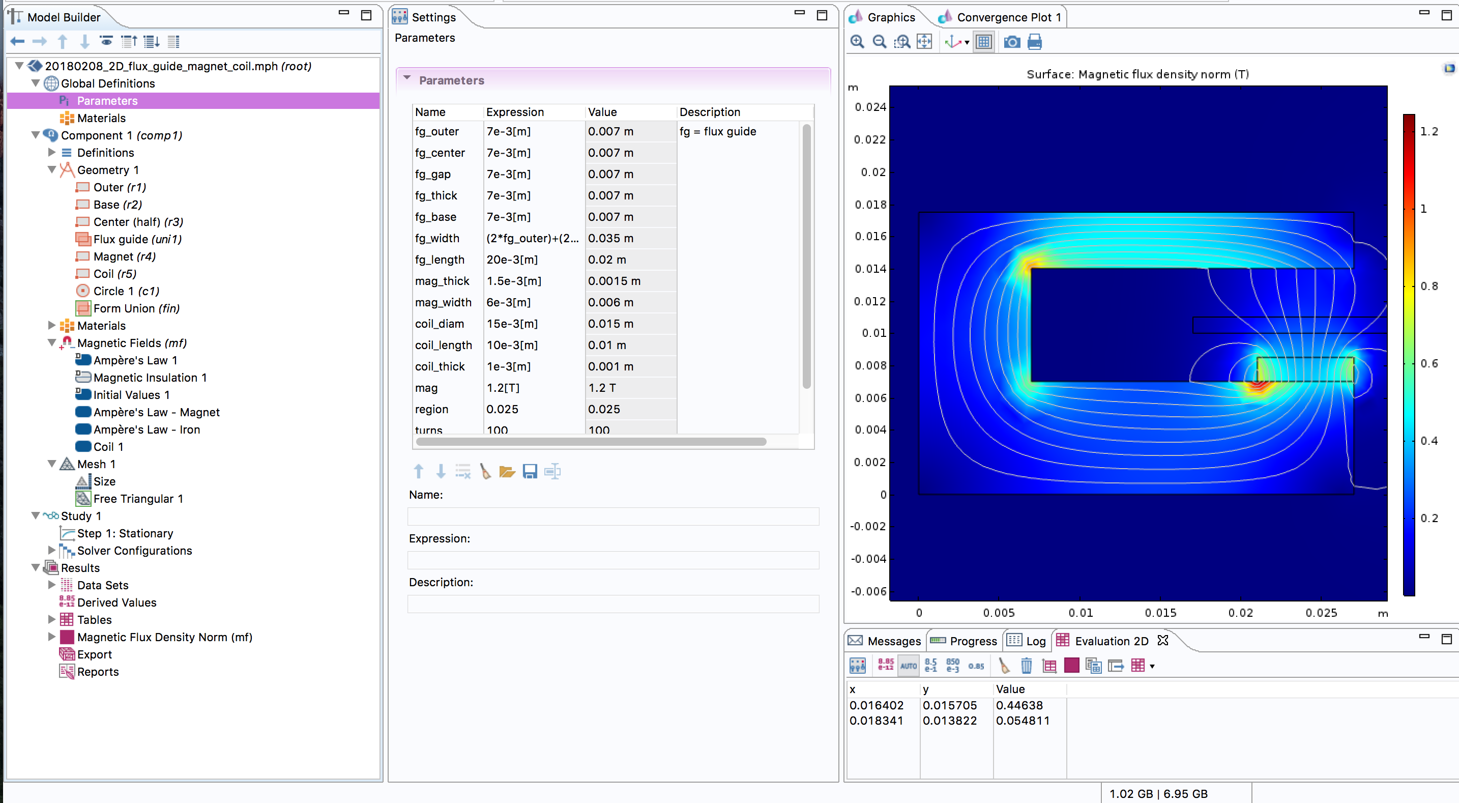
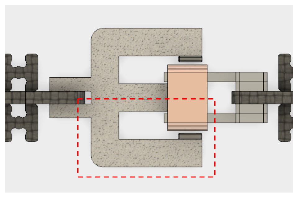
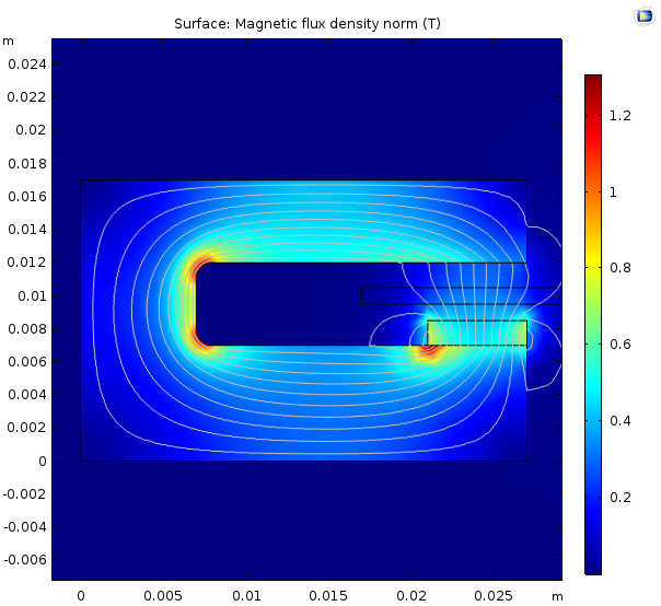
I started out by modeling half of the motor in 2D, the image below shows the region being modeled within the red dashed box.
In the plots below the upper part is half of the central core of the flux guide. After getting our motor setup I tried varying some dimensions and features to understand how these change the magnetic flux. The plot on the left shows the initial design, the plot on the right shows the design after making the air gap smaller.
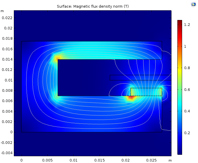
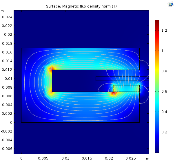
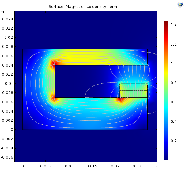
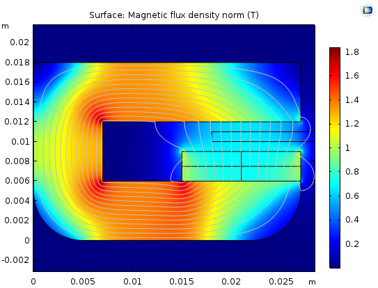
The plot on the left shows the design with fillets at the inside corners. The plot on the right shows the design with two magnets.
The magnets being used come from magnetman.com, they have a grade of N45 which according to the table in this link, translates to 1.32-1.37T.
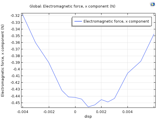
I carried out a parameter sweep for different displacements of the coil in order to output the horizontal force and determine the rough maximum magnitude that might be exerted. After changing the arragement of magnets and thickness of air gaps I found that a linear voice coil in this configuration will acheive a maximum of around 0.75 N of force. I fabricated a final pair of voice coil actuators however moving forward it seems as though a different design will be necessary.
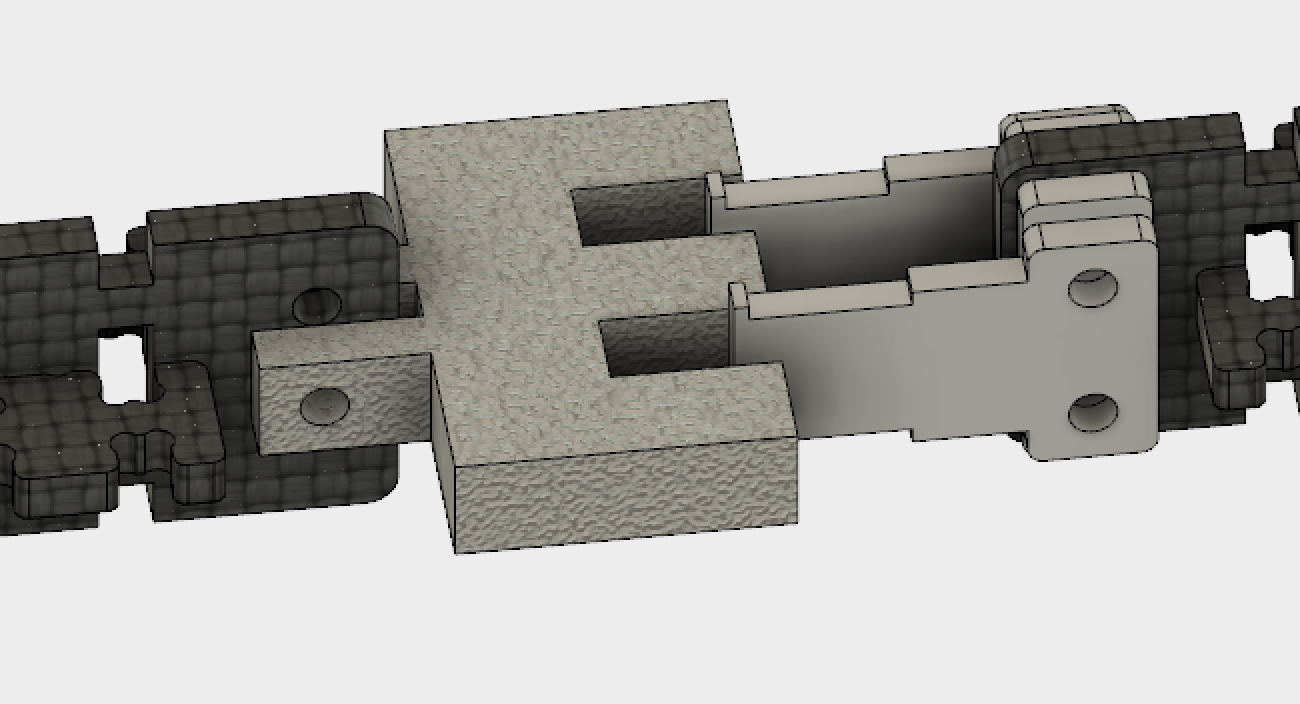
I've been including a stand in off the shelf linear actutor between two 3mm bolts. This design means that it's free to rotate at these locations and therefore doesn't maintain the regularity of the geometry in orthogonal axes to it's direction of motion. Therefore in future designs I need to make sure that I include constraints for this.
Patented by the Parker Pen company in 19xx, this mechanism utilizes springs, rotary and linear motion to produce two static and constrained states. There's a good description here.This transition requires an external force to actuate the mechanism but once initiated, creates secured non-powered end points. This 3D printable design demonstrates the mechanism. This type of mechanism would eliminate the need for power to hold the motor in position.
This would allow for a great amount of control, however the torque will probably not be sufficient.
It is possible to unroll the circular geometry of a stepper motor to create a linear motor. Again this wouldn't generate a great amount of troque.
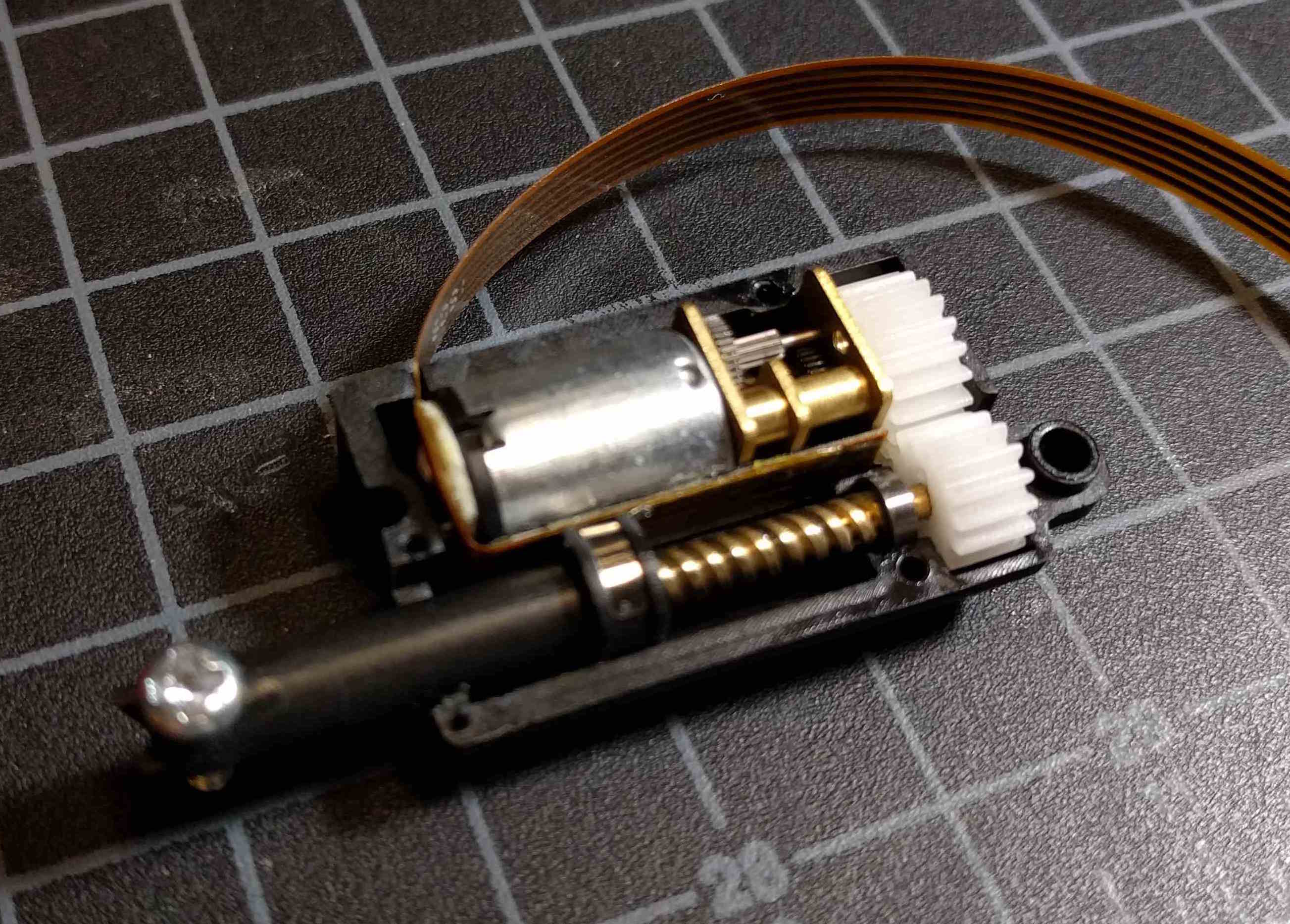
The linear actuators I've been buying (for $70) turn out be mini geared pololu motors with plastic gears and a lead screw. There seems to be a flex circuit running alongside the lead screw to carry out some kind of position sensing. I seems possible to fabricate these more cheaply using CBA machines.