In thinking about the design of the flexure for my system I've been trying to figure out the difference between introducing degrees of freedom intracellularly vs intercellularly (not sure that these are words). Intracellular DOFs might be interpreted as the double hinged pieces that I've been including. Intercellular DOFs might be interpreted as using parts that are identical in geometry to the structural parts but differ in stiffness (could also keep material the same and change thickness of strut). I feel that this could become part of the discussion on hierarchical cellular materials.
In the design of mechanisms, there is a general assumption that linkages are entirely stiff. However what the arrow above alludes to is that with the structural/mechanical systems that we're developing, there is a continum between a mechanism and a structure. For applications such as a shape morphing wing, the structure has a larger influence on the design. For a locomoting robot that interfaces with the ground, the mechanism might have a larger influence on the design.
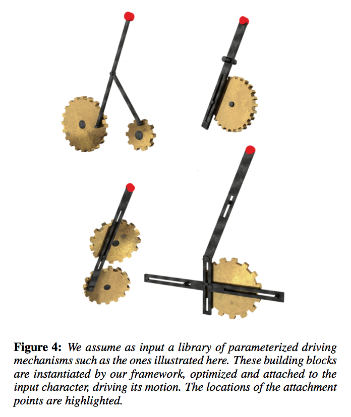
In order to understand what kind of degrees of freedom might be needed in the unit cell, it is helpful to look medium level at a basic library of mechansims and then a higher level at the resulting output functionlaity of the assembled system. Medium level functionality Work from Disney Research in "Computational design of mechanical characters" creates an interactive design system that produce mechanical assemblies based on user's input of a desired character's cyclic gait. Their system utilizes a library of parameterized driving mechanisms (see above). The output mechansism from this system isolate the character from the mechanism itself. This contrasts with the work that I'm doing in that I'm hoping to integrate the two. However it is helpful in providing an example mechanism library. High level functionality The PolyBot G3 was a self-reconfigurable system whose test cases were grouped into walking, snake-like and climbing.
In searching for test-cases for this system, there needs to be consideration for the structual and mechanical properties that my system offers beyond those of previous self-reconfigurable and self-assemblable robotic systems. This system offers better scalability given the simplicity of the kit of parts. This feature is described by the self-replicability factor coined by Zykov et al., measured by comparing the log probability of a machine spontaneously appeading in an environment to the log probability of it appearing, given that one instance already exists. For animals this is 10^20, for existing self-replicating robotic systems it is very low. Therefore this advantage might be demonstrated through the number of parts present in the system i.e. make a really really big thing. If the goal of this system is to allude to self-replication then perhaps an example of an assembly traversing another similar assembly is a good demonstration. This helps to constrain the range of motion required.
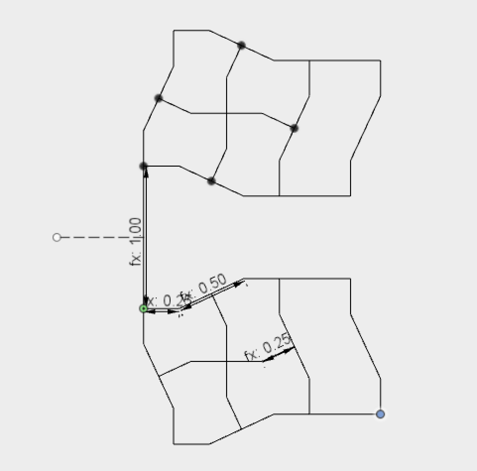
Assembly of the mechanism was almost easier to construct in Fusion in 3D however the constraints solver stumbled over the final joint. Will suggested that there were errors in the numerical rounding which meant that as a designer you need to introduce and additional redundant degree of freedom. So by making the final rigid joint into a revolute the maths all seemed to work out.
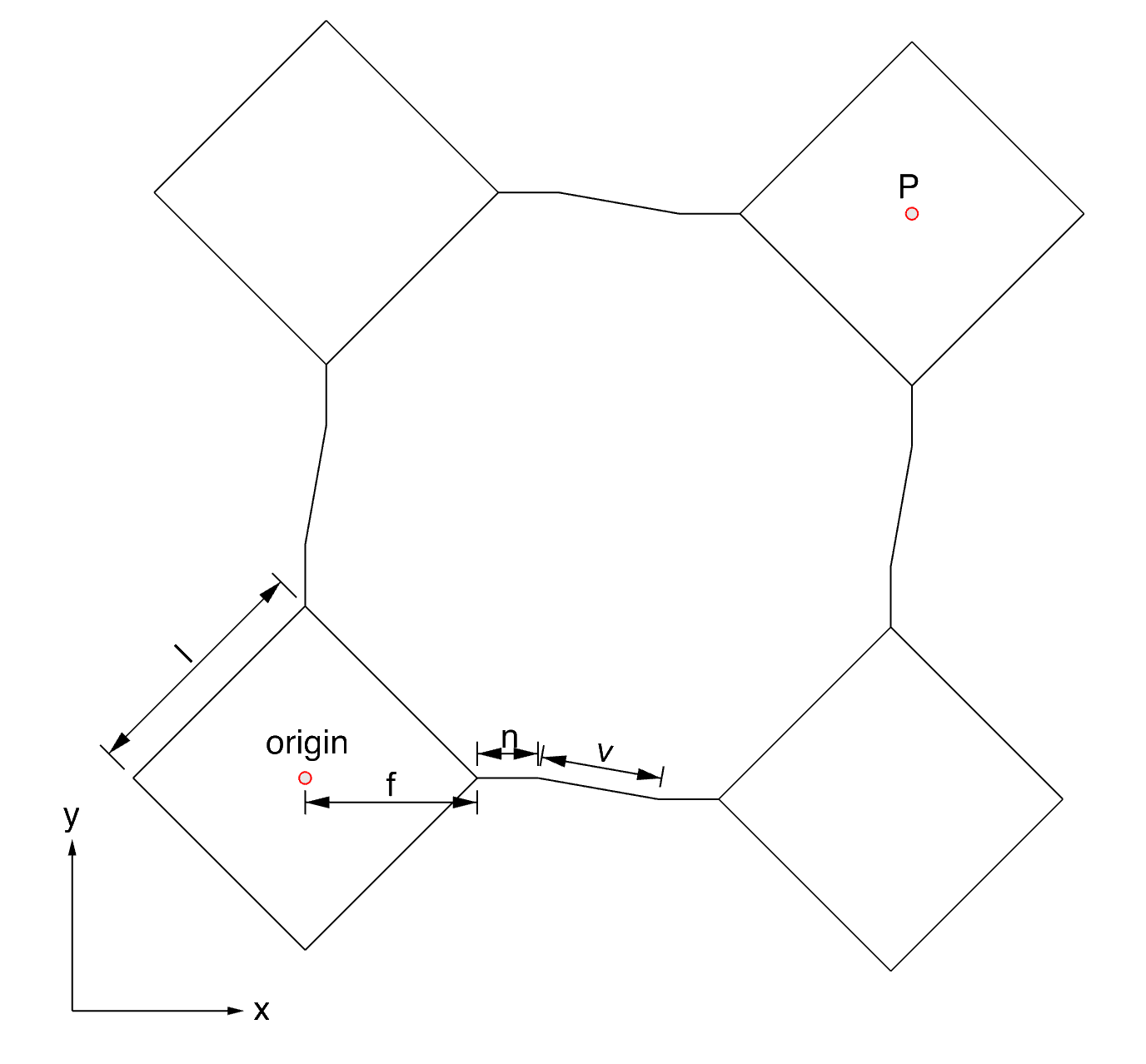
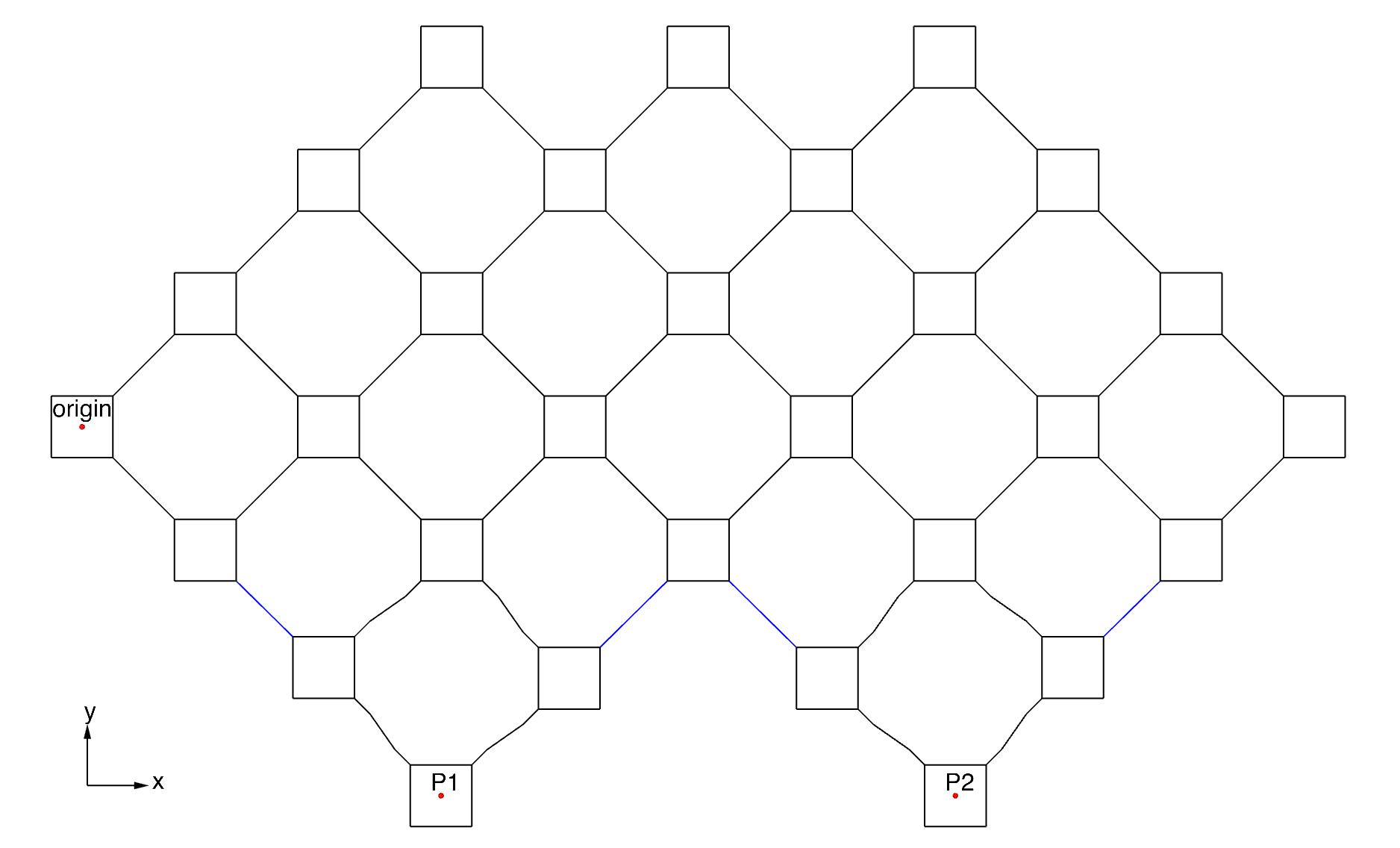
To make modelling simpler I have reduced the square corner pieces to point nodes. The extents of the gripper in the images below exagerate the available range of motion in the assembled structure. Also this type of design is limited in applying linkage designs directly to the pieces. However the point of these systems is to utilise one-bit acutation with single unit cells of the lattive to create large scale deformations. So the design process needs a certain level of hierarchy and modularity.
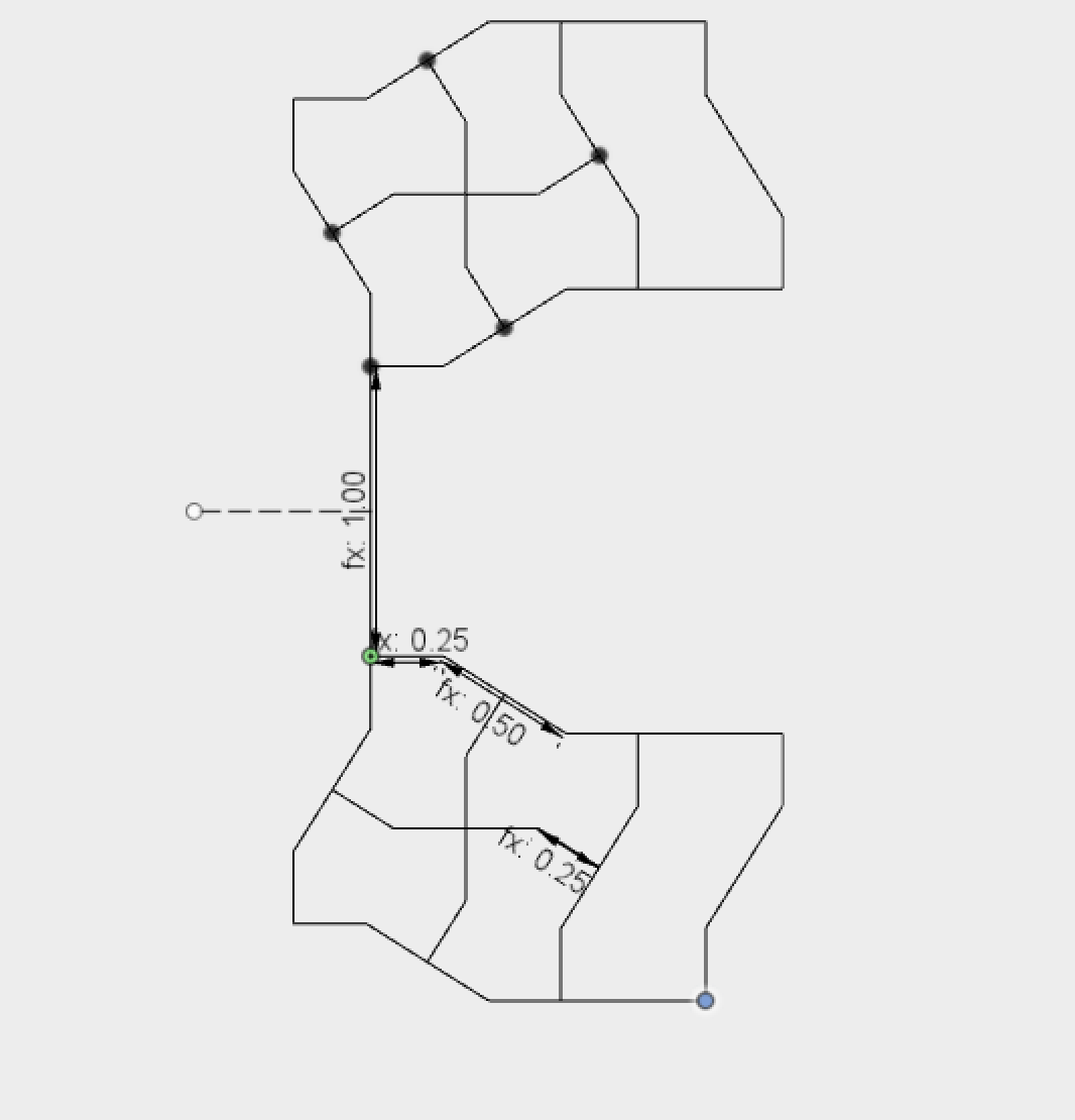
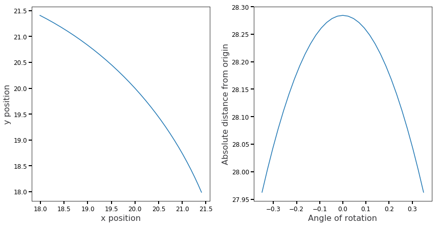
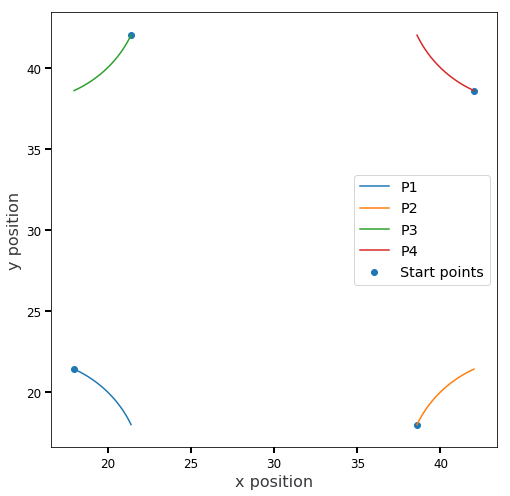
The graphs below show the 2D trajectory of point P. The left graph shows the range of motion give rotation of the flexures between +20 and -20 degrees. It shows that given a unit cell pitch of 10.0, point P deflects +/- ~ 17% of the lattice pitch. The graph on the right shows the radial distance of point P from the origin and demonstrates that this mechanism almost follows an arc but diverges ever so slightly from one.
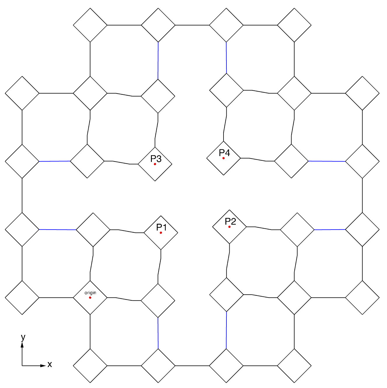
The sketch and graph below show a way of incorporating 4 walking motors into a single assembly, the graph shows how the trajectories of these motors might be coordinated. By placing some kind of gear in the center if might be possible to turn this into a stepper motor, I'm not quite sure how it would disengage at the end of a cycle but perhaps they would only go from +20 degrees to zero and in diverging slight from the arc they could disengage from the teeth.
Below is an assembly that might be expanded to produce a walker.
| The bottom right structure was kept uncut as a reference, the other mechanisms have assymetrical pairs of struts removed. | Again the bottom right structure was kept uncut, the other mechanisms have symmetrical struts removed. |
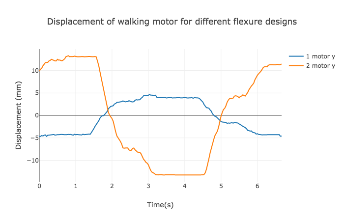
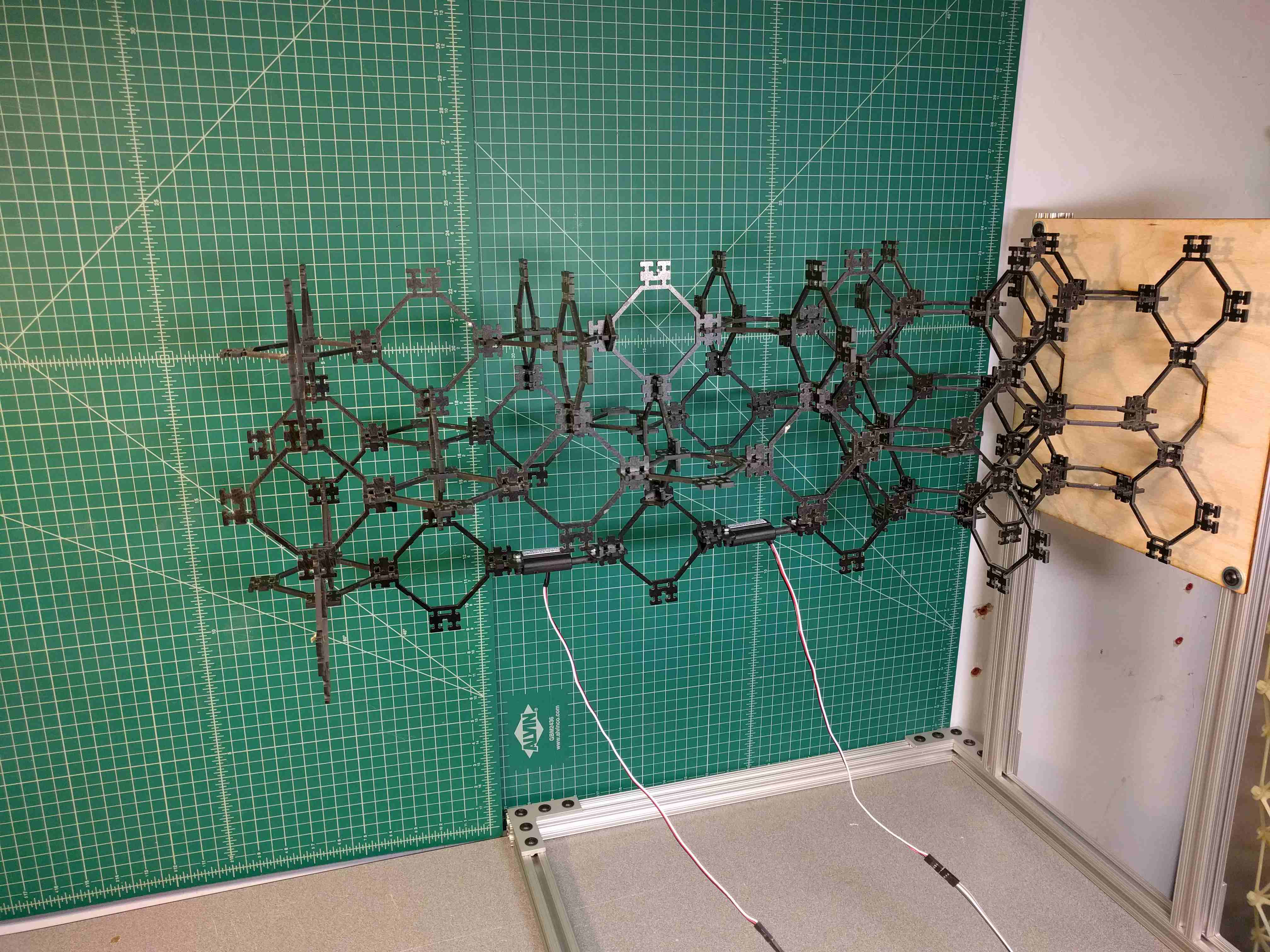
I have assembled two walking motors with different flexural parts. In doing so I realise that the 2 DOF hinged parts could represent a group of flexural parts that possess the same bulk material properties as the structural parts but have specific, low stiffness hinges. These parts could have 1,2,3 etc. hinges. The Delrin parts could represent a means by which to vary the overall stiffness of the part.
Whole structure is made from paper based phenolic composite parts.
Structural parts are made from paper-based phenolic composite parts, flexural parts are made from Delrin.
Structural parts are made from paper-based phenolic composite parts, flexural parts are also made from the same composite but contain two Mylar hinges. You can see that the lowest part is moving almost parallel to the grid lines of the mat.
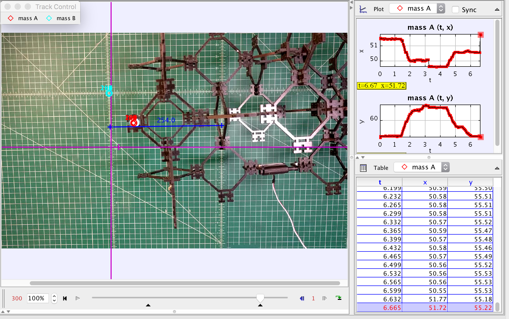
Longer versions of these videos were uploaded into software called Tracker. Using this I tracked the location of a point of the outermost corner of the flexural assembly and subtracted this from the coordinates of a stationary point to account for movement of the camera. The orientation of the coordinate axes are shown in purple below.
The range of motion is greatest for the 2DOF hinged flexure assembly. This also shows that there isn't a great deal of difference in displacement between the Delrin flexural pieces and the phenolic pieces despite the fact that the phenolic pieces are stiffer. However it should be taken into account that there is a large amount of delfection happening in the rest of the structure beyond the intended flexural pieces, therefore when specific hinges aren't present, everything deflects to a degree. The question is therefore
The plot shows that tip deflection scales approximately linearly with the number of actuators.